|Creative Engineering
home page|
|Table of contents |
Learning HighRoad |
Using HighRoad|
Reference|
| Previous |
Next |
Chapter 8
Profile
This chapter shows you how to define and adjust the longitudinal
profile and to instantly see the effects of this work on the cross
sections, quantities, mass diagram and plan view.
The
Profile window

When you select Profile from the Window menu, a window
named <Control line name> Profile will appear on your
screen. This window has markers on the left hand and lower edges of
the window. These markers display the chainage along the lower edge
and the elevation along the left hand edge, to indicate the portion
of the profile currently in view.
If you have not yet created or opened a terrain model and designed
a horizontal alignment you will not be able to select Profile from
the Window menu. Whenever the Profile window is open, HighRoad will
display the natural surface along the control line. See
Chapter 3,
Survey data and
Chapter
4, Terrain model
for information on how to create a terrain model.
Scrolling to a required position
You may have opened a terrain model and designed a horizontal
alignment but the window still appears blank. This may be because the
plot is off the top or bottom of the screen. You can choose Fit to
window, use the vertical scroll bar or change the scale to bring it
into view.
Scales
The profile can be displayed at a range of scales and vertical
exaggeration. Select the horizontal scale by choosing the one you
require from the View menu or by selecting Set scale... from the View
menu. The current scale is shown in the View menu with a tick against
it. The vertical scale is set according to the vertical exaggeration
(which you can select from the View menu). When you select Vertical
Exaggeration... from the View menu, a dialog box will appear. Type in
the vertical exaggeration required (it must be between 1:1 and 10:1).
If a scale of 1:1000 is chosen and the vertical exaggeration set at
10:1, the horizontal scale will be 1:1000 and the vertical scale
1:100. When a new scale or vertical exaggeration is selected the
profile is immediately redrawn at the new scale. You can change the
scales which are listed in the View menu. Choose Screen Scales...
from the Edit menu The scales you select must be in the range 1:50 to
1:20000. These scales will then be displayed in the View menu and
used for the display on the screen. You can also use the Zoom, Shrink
and Pan commands (and short cuts) to view different parts of the
profile.
Designing a road
grade line
 Positioning IPs
Use the mouse to position and visually adjust the vertical
intersection points (IPs). Enter vertical IPs in order from left to
right, that is, in order of increasing chainage. To start adding new
vertical IPs, choose New IP from the Profile menu. To locate the
first IP, position the pointer at the approximate location required
and drag. While the mouse button is down, the pointer will change to
a circle ( ) representing an IP marker. The
location of the IP and the grade will be displayed. (If you do not
want the location and/or the grade displayed, choose Hide Grades
and/or Hide IP Location from the Profile menu. The wording will
change to Show Grades and/or Show IP Location when the items are not
displayed.)
) representing an IP marker. The
location of the IP and the grade will be displayed. (If you do not
want the location and/or the grade displayed, choose Hide Grades
and/or Hide IP Location from the Profile menu. The wording will
change to Show Grades and/or Show IP Location when the items are not
displayed.)
As you drag, the location of the IP and the grade will be
continually updated. Release the mouse button when the IP is in the
correct position. When you add the second IP, a line showing the
straight grade between the IPs is drawn and continually updated as
you move the mouse. When you add the third and subsequent IP,
HighRoad not only draws the straight grade to the previous IP, but
also adds a vertical curve (VC) and displays its length and
radius.
Inserting or deleting IPs
You can also insert and delete vertical IPs. Insert IP... and
Delete IP... are available in the Profile menu when the Profile
window is in front, and two or more IPs have already been added. To
insert an IP find the number of the IP (by double-clicking on it)
after which you wish to insert an extra IP. Choose Insert IP... and a
dialog box which asks for this number will appear. The extra IP will
be inserted half way between the IP you nominated and the next IP.
You can then drag it to its correct location, or relocate it by
double-clicking it and editing the values shown in the dialog box.
To delete an IP, choose Delete IP... The cursor will change to an
X shape. Position the cursor over the IP to be deleted and click. The
IP will be deleted.
Adjusting the grading
At any time after a vertical IP is added, you can adjust its
position. Move the pointer to the IP you want to adjust and it will
change to a four pointed arrow ( ). Drag the arrow to the new location. The VCs at
this IP and either side of it will be redrawn to suit the new
location of the IP. HighRoad will also display the new IP position,
the new VC lengths and curvature and the grades each side of the
changed IP.
). Drag the arrow to the new location. The VCs at
this IP and either side of it will be redrawn to suit the new
location of the IP. HighRoad will also display the new IP position,
the new VC lengths and curvature and the grades each side of the
changed IP.
Fine adjustment of the grading
You can position any vertical IP precisely by specifying its
chainage and elevation or by specifying the grade from the previous
or next IP. To edit these values, double-click on the IP when the
cursor is a four pointed arrow ( ). A dialog box will appear as in
Figure 8-1.
). A dialog box will appear as in
Figure 8-1.
Figure
8-1
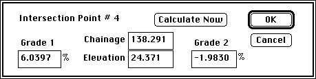
The dialog box shows the chainage and elevation of the IP, the
grade from the previous IP (Grade 1) and the grade to the next IP
(Grade 2). Grade 1 is not displayed for the first IP and Grade 2 is
not displayed for the last IP. The IPs are numbered in order from the
lowest to the highest chainage.
You can change the information in any of the fields displayed.
Click on the field or use the Tab key to move to the next field. Type
in the new number required. Either move to the next field, click
Calculate Now or OK and new values for two of the other fields will
be calculated automatically. If you change Grade 1, the elevation has
to be recalculated to suit the new Grade 1 and the Grade 2 has to be
recalculated to suit the new elevation. If the chainage is adjusted,
the grades either side are recalculated. If the elevation is
adjusted, the grades either side are recalculated. Click OK. The
gradeline will be replotted to reflect the new IP location.
Setting the VC length
HighRoad will automatically set each VC length so that it is as
long as possible without encroaching closer than halfway to the
nearest IP. You can override the automatic selection of the VC
length. Click on the VC length you wish to specify. A box will appear
around the VC length selected, as in Figure
8-2.
Figure 8-2
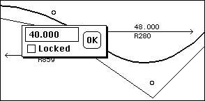
The VC length can be locked. If you check the box marked Locked
then this VC will remain at the length selected even if you move the
adjacent IPs. If it is unlocked, HighRoad will dynamically select a
VC length as you move the IPs. You can change the length you have
specified at any time by clicking on the text displaying the VC
length. If you do not require a vertical curve, set the length to
zero and lock it.
Vertical curvature
The vertical curvature along a grade line is displayed as either
equivalent radius (R) or K value. HighRoad is set up to initially
display the equivalent radius. If you want to change the measure of
vertical curvature that is displayed, choose Vertical Curvature...
from the Design menu. A dialog box will appear and you can select
either equivalent radius (R) or K value.
The formulae used to calculate vertical curvature are as follows:
equivalent radius
R = 100L / G
K value
K = L / G
where
L = length of vertical curve
G = algebraic change of grade over the length of the vertical
curve
Setting the maximum grade
HighRoad allows you to specify the maximum grade that can be used
when you are using the mouse to add IPs. Choose Maximum Grade... from
the Profile menu. A dialog box will appear and you can specify the
maximum grade required in the space provided. The grade will not
exceed the maximum value specified regardless of where you move the
mouse. The maximum grade is initially set at 25%, steeper than you
are likely to require.
Note: The grade is calculated using the location
of the pointer on the screen. You may find that the maximum grade is
sometimes slightly less than the value you have specified because of
the resolution of the screen.
Synchronised IPs

IPs on a control line which is part of an intersection can be
synchronised with connected roads. When IPs are synchronised in this
way, the vertical alignment is automatically adjusted to match
changes in connected roads.
For a side road, the first two IPs can be synchronised with the
through road. For a kerb return, the first two and last IPs can be
synchronised with both the through road and the side road. For a
cul-de-sac the first two, last two and middle IPs can be synchronised
with the attached road.
Adjusting a
group of IPs

You can adjust a series of vertical IPs as a group. To uniformly
raise part of the road by a fixed amount choose Adjust Profile IPs
from the Profile menu. A dialog box will appear and you can choose to
adjust the elevations or chainages of the IPs.
Automatic synchronisation of profile and plan
The chainages of vertical IPs are automatically adjusted to allow
for changes in length of the road due to adjustment of horizontal
alignment. When you make an adjustment to the horizontal alignment
which changes the plan chainages, HighRoad will automatically adjust
the vertical IPs by the same amount. This means the profile stays
attached to the same part of the terrain, rather than the same
chainage.
Therefore in most cases it will not be necessary for you to adjust
profile IPs to allow for changes in the length of the road.
Displaying cross sections

You can display a cross section at any point on the profile by
dragging the pointer to the chainage at which you wish to see the
cross section. As you drag the pointer, the cursor will change to a
dotted vertical line and the chainage will be displayed against this
line. Be sure to begin dragging from a blank space on the profile
otherwise you may inadvertently pick up an IP and move it, or select
a VC for editing.
When you release the mouse button, the cross section plot window
will come to the front and display the cross section at the chosen
chainage. If you have not designed a typical section, only the
natural surface will be displayed. If you have not designed a typical
section for the location requested, the nearest location for which a
typical section applies will be displayed. Refer to
Cross section
layout, Chapter 10 for more information about how to change the
appearance of the cross section displayed.
As you drag the cursor in the Profile window a line showing the
location of this section will be displayed in the Plan view if it is
currently visible.
Grading through a given point

In cases where it is necessary for the grade line to match a given
chainage and elevation (as might occur at a railway crossing,
underground obstruction, or under a bridge), HighRoad allows you to
adjust the grading to pass through a target. Choose Grade to
target... from the Profile menu. A dialog box will appear in which
you can enter the required chainage and elevation. Click OK. The
grading will be adjusted to pass through the point you entered.
HighRoad adjusts the IPs adjacent the target vertically in order
to bring the grade line on to target. The amount of adjustment of
each IP is proportional to its distance from the target.
High points and low
points

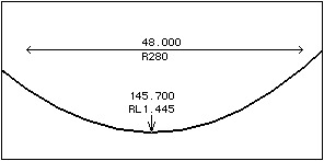
To display the location of high points and low points of the
profile, select Highs and Lows from the Profile menu. The location of
these points will be shown by an arrow together with the chainage and
elevation of the point (see Figure 8-3).
Figure
8-3
Batter limits

Batter limits may be displayed on the profile and used as a guide
when locating the grade line. This option is useful to ensure that
batters do not encroach on private property or past a given offset.
Before the batter limits can be calculated and displayed on the
profile, you need to add the limiting offsets to the typical
sections.
The batter limits are shown on the typical sections by selecting
the batter limit icon ( ) from the palette of
tools in the Typical Section window. (See
Batter limits Chapter 7, for
more details.) Once batter limits have been set up for the typical
sections, the limits of control line levels can be shown on the
profile. Choose Show batter limits... from the Profile menu. The
batter limits will appear in the Profile window as shown in
Figure 7-14.
) from the palette of
tools in the Typical Section window. (See
Batter limits Chapter 7, for
more details.) Once batter limits have been set up for the typical
sections, the limits of control line levels can be shown on the
profile. Choose Show batter limits... from the Profile menu. The
batter limits will appear in the Profile window as shown in
Figure 7-14.
Culverts

You can show the locations of culverts on the Profile. Choose New
culvert from the Profile menu and the cursor will change to a pipe
icon ( ). Click on the profile at the
location where you want to place the culvert. A dialog box will
appear allowing you to specify information about the culvert (see
Figure 8-4). You can specify chainage,
invert level, and the number and spacing of culvert cells.
). Click on the profile at the
location where you want to place the culvert. A dialog box will
appear allowing you to specify information about the culvert (see
Figure 8-4). You can specify chainage,
invert level, and the number and spacing of culvert cells.
Figure
8-4
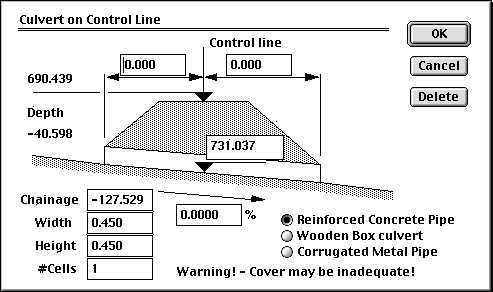
Culverts specified in this manner will appear on the profile
drawings, whether printed, plotted or exported.
Earthworks
balance/full bench levels

Markers to aid in producing a balanced or full cut design can be
shown on the profile. See
Balanced
earthworks and
Full bench
construction for details about these options.
| Previous |
Next |