![]()
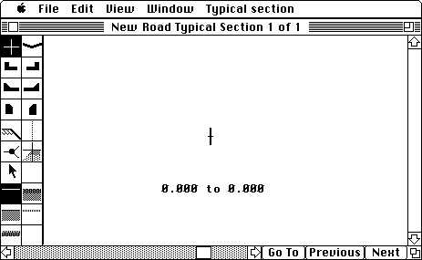
When you select Typical Section from the Window menu, a window named <Control line name> Typical Section 1 of 1 will appear on your screen (as shown in Figure 7-1).
|Creative Engineering home page| |Table of contents | Learning HighRoad | Using HighRoad| Reference| | Previous | Next |
This chapter shows you how to design typical sections. HighRoad allows you to specify the shape of the finished surface, the thickness and material of the surface layers and the dimensions of edge types, such as kerb and gutter. You can specify as many different typical sections as you require along the length of road. HighRoad will interpolate between sections to model twisting and varying-width pavements. You can define special pavements or batter slopes which occur only in a particular strata. When you design a typical section which will be useful for future projects, you can add it to a Typical Section library.
When you select Typical Section from the Window menu, a window named <Control line name> Typical Section 1 of 1 will appear on your screen (as shown in Figure 7-1).
This window has a palette of HighRoad tools on the left side of the window. These tools are used for designing typical sections. The icons in the tool palette represent edges (for example kerb and gutter) and surfaces (for example, pavements). The window also has a chainage range initially set at zero and a control point (
).
Note: Depending on the size of your screen, the icons may appear in a single column rather than in two columns as shown here.
Control point
The control point represents the elevation of the line along which the vertical grading is applied. In many cases, this will be the centre line of the road. In the absence of a design profile the control point of the typical section will attach to the ground
Edge types
Cross cursor (used where no edge type is required)
Vee drain
Left and right kerb and gutter
Left and right mountable kerb and gutter
Left and right mountable kerb
Batter point
Batter limit
Split Point
Sloped pavement edge
Arrow cursor (used for editing offsets and crossfalls)
Click on an icon to select it as the active edge type. HighRoad will highlight the active edge type and the cursor will assume the shape of the active edge type when it is in the drawing region.
Surface types
Surface types appear in the palette of tools below the edge types. A surface type is selected by clicking on it with the mouse. The active surface type will be highlighted and the surface can be drawn on the screen using an edge type to position it.
Untreated
Pavement
Shoulder
Grass
Topsoil and grass
Additional pavement
Additional pavement
Additional pavement
The shape and properties of a typical section are drawn using the mouse in conjunction with the palette of tools on the left side of the Typical Section window. Each link in the shape of a typical section requires an edge and surface type (to specify its properties) and an offset and crossfall (to specify its shape).
Selecting edge and surface types
Click the required edge and surface type icons in the palette of tools to specify the properties of the cross section. The icons are highlighted and the cursor assumes the shape of the edge type chosen. When the Typical Section window is first opened, edge type is the cross cursor and the untreated surface is the surface type. To specify the dimensions and characteristics of an edge or surface type, double-click on the icon. (More detailed information about the properties of edge and surface types is described on pages 7-5 to 7-10.)
Specifying offset and crossfall
Drag the cursor to the approximate position required to specify the offset and crossfall. These dimensions (which are measured from the previous edge to the edge now being added) will be continually updated as you move the cursor. The offset is displayed in metres or feet and the crossfall is displayed as a percentage to one decimal place.
You can change the scale by choosing the one you require from the View menu or by selecting Set scale... from the View menu.
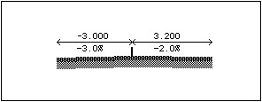
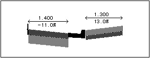
Figure 7-2 shows a sample cross section where two links have been added. In this case, the cross cursor has been selected because no edge type is required.
Adjusting the typical section
You may find it difficult at first to position the link precisely. HighRoad allows you to edit your design to a specified offset and crossfall. You may also change the surface or edge type.
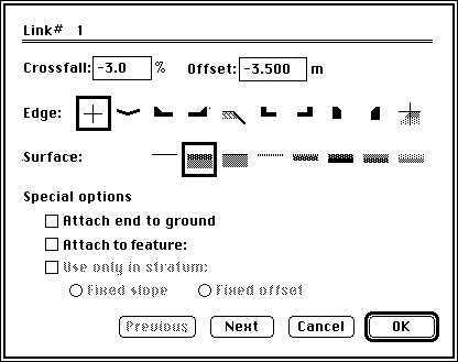
To edit an offset or crossfall click on it. A dialog box will appear with the dimension selected and the edge and surface types of that link indicated as shown in Figure 7-3. Select the number you wish to change. The cursor will change shape to an I-beam and you can type in the new number from the keyboard. The currently selected edge and surface types are enclosed with a box. To change to another type, click the required edge or surface type. Click OK. The typical section will be redrawn, showing the changes.
You can change other links in the same typical section by using the Next and Previous button. These buttons are also useful to get to a link that is small and difficult to click on.
Adding more links
The first link that you add will be connected to the control point in the centre of the window. Additional links can be connected to the edge of the last link added on that side of the typical section or to the other side of the control point. As you move the cursor across the part of the typical section already drawn, it will change shape to an arrow to remind you that you cannot add another link at this point.
Note: If you have a series of typical sections, it is important to add the links in the same order for each typical section. (See details in Chapter 23, Troubleshooting.)
Commonly used typical sections can be stored in a library for easy pasting into a road design. See Typical Section library, page 7-23.
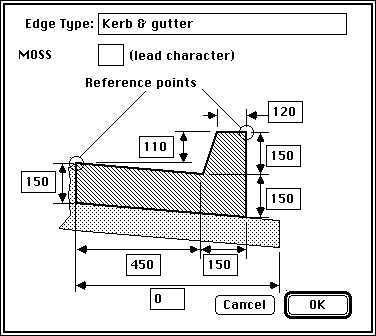
Detailed dimensions are available for each kerb type and the vee drain. Double-click on the icon and a dialog box will appear on the screen. The dialog box (Figure 7-4 is an example) displays a drawing of the edge type that it refers to. It contains the following information about these edge types:
name
dimensions
cross section view (not to scale)
location of reference points
extra width of pavement
You can change the name and dimensions using the usual editing techniques.
Name of edge type
Drag to select the characters you wish to change and type in the new text.
Dimensions
The dimensions displayed in the dialog box are used to draw the edge type on the typical sections and the cross sections. The shape of the edge type will be depicted in the cross section accurately at whatever scale you choose and will change shape as you change the dimensions. (The icons and cursor are diagrammatic only and do not change shape to reflect changed dimensions or scale.) The dimensions are also used in conjunction with the reference points to calculate the location of the start of the surface joining the edge type. (See Reference points, page 7-7 below.) To change the dimensions of the edge type, use Tab to move to the next dimension, or use the mouse to click on the next dimension you wish to edit. Enter the dimensions as millimetres (or feet with up to two decimal places).
Cross section view
The cross section view of the edge type indicates the general shape of the edge type. Although it represents the typical shape of each type, it does not restrict the dimensions you may specify. You may specify dimensions for a shape of the same form but with different proportions to the one depicted in the cross sectional view. For example you could change the dimensions of the edge shown in Figure 7-4 to represent a concrete traffic barrier which is much taller than the shape depicted.
The reference points for the kerb and gutter edge type are illustrated in Figure 7-4. These are the points to which the adjacent surfaces are attached and from which the crossfall and offset are calculated. Figure 7-5 shows where two links of a typical section have been drawn.
The edge type used is a kerb and gutter and the two surface types connect at the reference points on the kerb and gutter. The offsets are measured from the closest reference point on the previous edge type (or the control point) to the closest reference point on the edge type being added. In this example, the right edge was located using the cross cursor which is used only to position a surface layer where no edge is required. If the surfaces consist of one or more layers as shown in Figure 7-6 the dimensions are still calculated from the same points and the top of the layer is joined to the reference points. The thickness of the surface layers is always shown below the finished surface.
The only difference between Figure 7-5 and Figure 7-6 is the type of surface that has been used. The offset, crossfall and edge type are the same for both examples. The distance between the two surfaces in both examples is determined by the dimensions of the kerb and gutter.
Extra pavement width
You may need to extend the pavement under the kerb and gutter edge types. This is illustrated in Figure 7-4. You can nominate the distance that the pavement extends under the edge type using the usual editing techniques. When the distance is zero the pavement ends where the edge type begins.
If you intend to export the road design in MOSS GENIO format you may wish to nominate the leading character to be used when naming MOSS strings. For example you may want to have all strings representing kerbs start with the letter K. The character you provide here will be the first character of a four character MOSS string.
When exporting a road as a MOSS file, the naming convention for strings can now be controlled by you. A single character can be nominated as the first character for MOSS string names for edge types and surface types as described here. MOSS string names have four characters which are made up as follows:
1st character
This is the character specified by you.
2nd character
This is the control line number. Control lines 1 to 9 are denoted by the numerals 1 to 9. Control lines 10 to 35 are denoted by the letters A to Z. All control lines after 35 are also denoted by Z.
3rd character
This indicates whether the string is left or right of the control line and is denoted L or R
4th character
This is a counter of the number of strings on this side of this control line. The numbers used are 1-9 for strings 1 to 9 and A-Z for strings 10 to 35. Strings in excess of 35 are denoted by Z
Consider this example which may help clarify how this works. A kerb denoted by K, on the left side of control line 5, and the 3rd MOSS string on the left side of this control line would be:
K5L3
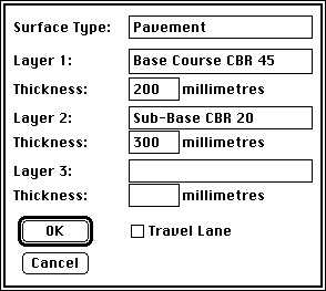
Each surface type can consist of one, two or three layers of material and the thickness and name of these layers can be specified. Double-click on the icon of the surface type and a dialog box will appear as in Figure 7-7. The thickness of the layers is used to calculate earthworks, pavement quantities and subgrade levels. It is also used to display the pavement on the typical sections and cross sections at the selected scale.
The surface type named in the dialog box allows you to differentiate between surface types. Earthworks quantities are calculated to the underside of the bottom surface layer. The surfaces can represent pavement, topsoil, concrete paving, interlocking blocks, concrete lining on a drainage channel and so on.
The dialog box also allows you to indicate if the surface is a travel lane. Superelevation (if required) will be applied to all travel lanes. (See Superelevation, in Chapter 9, Transitions.)
The edge types related to cut and fill batters have different features from other edge types. Batter points must be used in conjunction with split points.
Split point
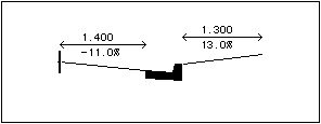
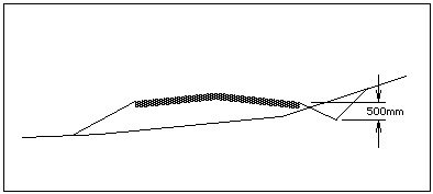
The split point is a special edge type which has to be used when you require batter slopes. An example of its use is where a table drain is required in cuttings and not in fills, as shown in Figure 7-8.
The point on the cross section where the cut and fill shapes split is the outer edge of the pavement. A split point is used here. The order in which the links are added determines the order in which HighRoad checks for which batter slope to use. If you add the table drain and cut batter first, then the fill batter, HighRoad will check for the table drain and cut batter before a fill.
This distinction is significant in the case of a low fill. In Figure 7-8, the drain is 500 mm deep to ensure that the pavement layers are free draining. Where the road is in fill of less than 500 mm, both the cut and fill batters could be applied. Because the drain is the preferred option, the drain and cut batter should be added to the typical section first. In this case, HighRoad checks for a cut batter first. Because it can intersect the cut batter with the natural surface, HighRoad does not check for a fill batter.
Batter links
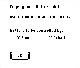
Batter points must be used in conjunction with split points. The batter links can be used to define both a cut and a fill batter to connect to the same point. HighRoad will select the appropriate batter (cut or fill) for each cross section to be calculated and drawn. You may also specify either the slope or the offset as the fixed dimension for the batter. This can be done by double-clicking on the icon and making the appropriate choice in the dialog box which will be displayed (as shown in Figure 7-9).
In the case of the fixed slope batter (probably the most common case) HighRoad will extend the batter at the specified slope until it intersects the existing surface. If it does intersect with the existing surface, HighRoad will return to the split point, and then search for another batter link. (See page 7-15 for a further discussion about batters.) Choosing slope as the method for batter control will ensure that its slope will remain constant and its point of intersection with the ground surface will vary in offset from the previous edge as the relative level between the ground and road varies. By choosing the offset to be fixed, the batter slope will vary so that the point of intersection with the ground surface will always be a constant offset from the previous edge. To indicate which option is currently in force, HighRoad displays either the slope or the offset (as appropriate) when the batter is being added.
Note: If you choose a fixed offset batter, HighRoad can always intersect it with the existing surface. Where you have more than one type of batter condition, be sure to add the fixed offset batter last.
Complex batter shapes
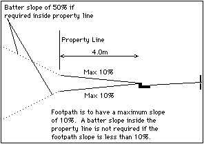
The different batter options can be mixed in the one typical section to model a complex batter shape. This is useful when the batter treatment varies depending on the depth of cut or fill as in Figure 7-10.
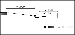
The footpath can have a maximum of 10% crossfall. Where the natural surface is close to the elevation of the kerb (in this example within 400 mm, or 10% of 4 m), the footpath would be sloped to meet the natural surface at a point 4 m from the kerb. To model this situation, a batter with a fixed offset of 4 m would be specified. This is shown in Figure 7-11.
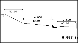
Where the road is in deeper cut or fill, that is, the natural surface is more than 400mm above or below the kerb, additional batter types are required. In the case of a fill, the batter is controlled by slope as shown in Figure 7-12.
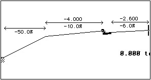
In the case of a cut deeper than 400 mm, the batter treatment is shown in Figure 7-13. This batter is also controlled by slope.
These three batter types must be incorporated in the same typical section so that the correct batter is selected. HighRoad will check each batter type in the order in which you add them to the typical section. When it finds one which intersects the natural surface, it stops checking. In this example, the fixed-offset batter must be added last. If added first, it would be used in all cases because a fixed-offset batter can always intersect with the natural surface. The correct typical section for this example would be drawn in the following order: kerb, split point, cut batter, fill batter and fixed offset batter.
Complex batter shapes can be stored in a library for easy pasting into a road design. See Typical Section library, page 7-23.
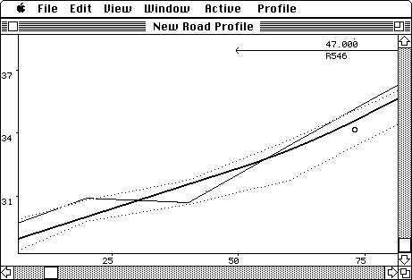
This tool is used as an aid to design when the limits of batters are critical. The batter limits are not plotted on cross sections but generate limit lines which are plotted as dashed lines on the profile (as shown in Figure 7-14). These lines represent the upper and lower limits of the control line level that is, if your design allows the control line level to fall between these limits, then the batters will not fall outside the limits set up on the typical sections.
In some cases where the natural cross slope is steep, it may not be possible to meet the batter limits (given the batter slopes and section shape chosen). In this instance, the upper and lower limits will coincide and appear as one line. This line represents the elevation of the control line which will produce batters exceeding the limits equally on each side.
Initially the chainage range of a typical section is from 0.00 to 0.00. You can change this range to indicate the length of road over which a typical section applies. Click on the chainage and a dialog box will appear. Type in the required range. This option is useful for designing roads which have varying cross section shapes over their length. In such a case a series of typical sections would apply over the length of the road. Where one cross section applies for the full length of the road, the chainage range should cover the length of the road.
Drawing a series of typical sections
You can draw a series of typical sections with varying properties which apply to one road. HighRoad will interpolate between typical sections. To assist in the construction of a series of typical sections you can cut, copy, paste, clear and duplicate typical sections.
Commonly used typical sections can be stored in a library for easy pasting into a road design. See Typical Section library
Adding and deleting typical sections
Choose Duplicate Typical Section from the Edit menu to add another typical section. A copy of the current typical section will be inserted after the current typical section, ready for you to make the required changes. To remove all the information about the displayed typical section, choose Clear Typical Section. Only the control point (
) will remain.
Choose Cut Typical Section to remove a displayed typical section from the Typical Section window. A copy of that typical section is placed on the clipboard. The remaining typical sections are renumbered if necessary.
Choose Copy Typical Section to place a copy of a displayed typical section onto the clipboard. The copy on the clipboard can then be pasted elsewhere in the Typical Section window or pasted into another application. Use Paste Typical Section to replace the displayed typical section with a copy of the typical section on the clipboard.
Pavement widening or tapering
You can widen or taper pavements by drawing a series of typical sections with varying pavement widths. The pavement widths will be interpolated between typical sections. This may be useful for pavement widening on curves, climbing or turning lanes and shifting a pavement crown. The technique described below can also be applied to any link on the cross section. For example, a footpath could be widened, a drainage ditch tapered, or a shoulder introduced and tapered to its full width.
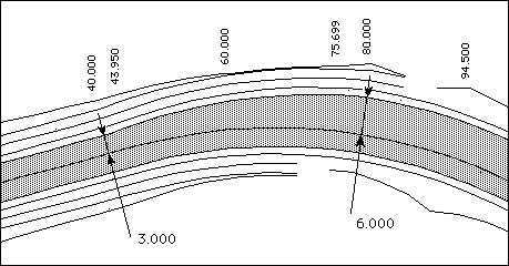
Consider the case where a wider pavement is required for a climbing lane. The plan view is shown in Figure 7-15. From chainage 0.000 m to 40.000 m, both travel lanes are 3.000 m wide. From chainage 80.000 m onwards, the left pavement is 6.000 m wide in order to accommodate the extra lane. Between chainages 40.000 m and 80.000 m the left pavement widens gradually from 3.000 m to 6.000 m.
This can be achieved by drawing two typical sections one from chainage 0.000 m to 40.000 m (where the left pavement is a constant 3.000 m wide) and another from 80.000 m to the end of the climbing lane (where the left pavement is a constant 6.000 m wide).
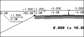
First draw the typical section for the chainage range 0.000 to 40.000 m, as shown in Figure 7-16. This typical section will be named <Control line name> Typical Section 1 of 1. Choose Duplicate Typical Section from the Edit menu.
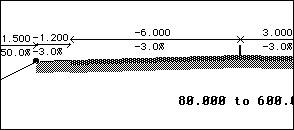
A copy of the first typical section will be made. This second typical section will be named <Control line name> Typical Sections 2 of 2. Change the range of this typical section. Click on the chainage range and type 80.000 and 600.00 in the appropriate places in the dialog box. Change the width of the left pavement to 6.000 m. Change the width of the offset from 3.000 to 6.000. Figure 7-17 shows the shape of the typical section after these changes have been made.
The left pavement of the cross section shape will be widened between chainage 40.000 m and chainage 80.000 m. You can verify this by displaying a series of cross sections over the range of this widening, by viewing the plan, or by viewing the drive through simulation. HighRoad uses a linear interpolation to calculate the pavement width at any point in between chainage 40.000 m and chainage 80.000 m.
Typical sections in a rock stratum
Note: This option is available only if you have purchased the license to use the Extra DTM module. This module is included in HighRoad Pro and optional in the other models.
A rock stratum can be created when the Plan window is in front. (See Adding another stratum Chapter 4) This stratum will appear in cross sections displayed on screen, or printed or plotted.
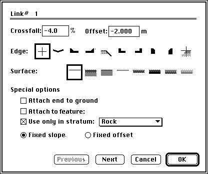
Links in the typical section can be specified as appearing only in the rock stratum (or any other layer you specify). Click on the offset or crossfall of the link you want to make strata sensitive. A dialog box will appear as shown in Figure 7-18.
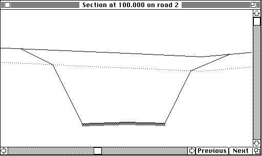
The end of the link will be attached to the surface of the rock at either a fixed slope or fixed offset from the end of the previous link. This is useful in the case shown in Figure 7-19 where batters in rock are steeper than those in granular material. In the example shown in Figure 7-19 the link is extended at a fixed slope until it reaches the surface of the rock.
Attaching a typical section to the ground
A special type of typical section link can be attached to the ground. You can use this type of link to make some design situations easier. For example, for a project requiring shoulder widening, it is usual that the new work attaches to the edge of the central pavement which is already constructed. Below is a simple example showing how a typical section suitable for shoulder widening may be created.
Firstly, no design profile is needed. In the absence of a design profile, the control point of the typical section will attach to the ground. This means that the control point of cross sections will be attached to the centre of the existing pavment (assuming that the horizontal alignment follows the centre line of the existing pavement). The first link either side of centre line represents the existing pavement. So this link would usually be drawn with a thickness of zero for all pavement layers.
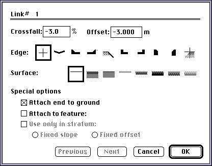
The end of the central links should be attached to ground. Click on the link that that you wish to attach to the ground. A dialog box as shown in Figure 7-20 will appear. Check the box labelled Attach end to ground. Repeat for the other link. In this way the central portion of the typical section matches the shape of the existing road and the vertical alignment of the new work will simply follow the existing edge of pavement.
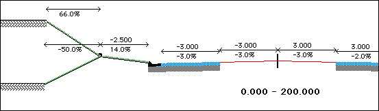
So far the typical section represents the shape of the existing pavement which will be retained. Attached to the edges of this pavement will be the new shoulders. The links for new shoulders and whatever treatment is required at the edges are added next. These links are drawn just you would draw them for any typical section. The final result is a typical section looking similar to Figure 7-21.
Attaching a pavement to a feature
A special type of typical section link can be attached to a feature. You can use this type of link to make some design situations easier. For example, where the batter slope of a road or pad is to finish at a known feature line such as a concrete edge, you can have a link that is anchored to this edge, no matter what the offset (within limits) or slope required to match this. The slope and offset of that link will vary as required to match with this feature.
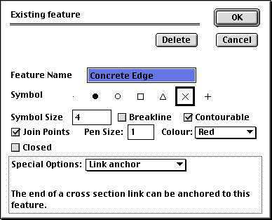
To create such a link, first create the feature string that you wish to use. Choose New feature string... from the Plan menu. A dialog box as shown in Figure 7-22 will appear. Be sure to give it a descriptive name that will help you identify this particular feature easily. Choose Link anchor from the Special Options pop-up menu to specify it as a feature to which a link can anchored. Alternatively edit an existing feature to specify it as a feature to which a link can anchored See Editing a feature string, Chapter 4 for details)
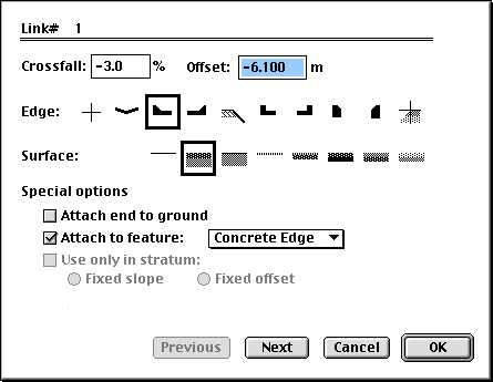
The next step is to edit the link that you wish to anchor to this feature. Go to the Typical Section window and click on the link that that you wish to attach to the feature. A dialog box as shown in Figure 7-23 will appear. Check the box labelled Attach to feature. Select the feature that you wish to anchor the link to from the pop-up menu listing all the available features to which a link can be anchored.
When creating cross sections that are based on such a link, HighRoad limits the search for a suitable feature to the cross section width. In the case of cul-de-sacs and intersections the attachment feature is invisible and is created and moved automatically as necessary when the cul-de-sac is moved or adjusted.
Note: Be very careful if you edit anchored links that are created automatically. Such links and the matching feature are changed atomatically when the cul-de-sac is moved or some aspect of the design is varied. If you alter such a link or its matching feature, HighRoad may not be able to correctly make adjustments later, and you may get unexpected results.
Commonly used typical sections can be stored in a library for easy pasting into a road design. You can use a single typical section library which holds all the standard typical sections that you commonly use. Alternatively, you may find it useful to create a number of Typical Section libraries to store groups of typical sections. When HighRoad is started, the Typical Section library last used is automatically loaded for use.
Storing a typical section in the library
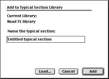
When the Typical Section window is active and the typical section you wish to add to the library is displayed in the window, choose Add Typical Section to library from the Typical Section menu. A dialogue box will appear as in Figure 7-24.
The dialog box (as shown in Figure 7-24) shows the name of the currently loaded Typical Section library, in this case Road TS library. If you wish to load another Typical Section library, click the Load... button. You will be presented with a dialog box from which you can select the appropriate Typical Section library. If you click Cancel you will be asked if you wish to create a new Typical Section library. You can name the typical section to suit your needs. Choose a name which will be meaningful later because when you wish to paste from the typical section library you will select from a list of typical section names.
Pasting a typical section from a library
A typical section can be pasted into a road design project when the Typical Section window is active. If there are multiple typical sections for this road, move to the typical section where you wish to paste the library section. The typical section from the library will be inserted before the current typical section.
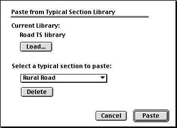
To paste from the Typical Section library, choose Paste from Typical Section library from the Typical Section menu. A dialog box will appear as shown in Figure 7-25. It shows the name of the currently loaded Typical Section library, in this case Road TS library. If you want to load another Typical Section library, click the Load... button. You will be presented with a dialog box from which you can select the appropriate Typical Section library. (If you click Cancel you will be asked if you wish to create a new Typical Section library.)
Select the appropriate typical section from the pop-up menu and click Paste. (The pop-up menu lists the names of all the typical sections in the current library.) The typical section named in the pop-up menu will be inserted before the current typical section. If you wish to delete the typical section displayed in the pop-up menu, click the delete button.
| Previous | Next |