|Creative Engineering
home page|
|Table of contents |
Learning HighRoad |
Using HighRoad|
Reference|
| Previous |
Next |
Chapter 4
Terrain model
This chapter shows you how to create a terrain model
from the survey data. You will see how to display the terrain model
in various ways.
The Plan
window

Once the survey data has been converted into HighRoad format (see
Chapter 3, Survey data) the points are displayed in the Plan window,
initially shown as dots and a point number. Zoom, Shrink and Pan
tools (and short-cuts) and Fit to window are available in the Plan
window for faster and easier navigation.
Zoom
Choose Zoom from the Edit menu and the cursor changes to
a magnifying glass which contains a plus ( ). Click the
point of interest and the view will be magnified by a factor of 2.
The point of interest will be in the centre of the window. As a
short-cut, you can select Zoom using the Command (
). Click the
point of interest and the view will be magnified by a factor of 2.
The point of interest will be in the centre of the window. As a
short-cut, you can select Zoom using the Command ( ) key on Macintosh or the Alt (
 ) key on Windows.
Shrink
Select Shrink and the cursor changes to a magnifying glass which
contains a minus ( ). Click the point of
interest and the view will be shrunk by a factor of 2. The point of
interest will be in the centre of the window. As a short-cut, you can
select Shrink by simultaneously using the Command (
). Click the point of
interest and the view will be shrunk by a factor of 2. The point of
interest will be in the centre of the window. As a short-cut, you can
select Shrink by simultaneously using the Command ( ) and Shift (
 ) keys on Macintosh or the Alt (
 ) and Shift (
 ) keys on Windows.
Pan
Select Pan from the Edit menu and the cursor will change to a hand
( ). Drag the view in the direction
you want to move it. The view will be redrawn in the new position
when you release the mouse button. As a short-cut, you can select Pan
by using the Option (
). Drag the view in the direction
you want to move it. The view will be redrawn in the new position
when you release the mouse button. As a short-cut, you can select Pan
by using the Option ( ) key on Macintosh and the
right mouse button on Windows.
) key on Macintosh and the
right mouse button on Windows.
Fit to window
Select Fit to window from the View menu and HighRoad will choose
the largest possible scale so that all the terrain points in a
project can be seen in the window.
Feature
strings

Natural and constructed features represented by points on the
terrain model can be displayed in different ways by using feature
strings. Features are defined by joining together the points on the
terrain model which belong to that feature. HighRoad can
automatically join feature points together based on a code associated
with each point.
Natural features such as ridges and gullies, and man-made features
such as drainage ditches and road shoulders can be modelled by
defining them as breaklines. These are features which define the
shape of the terrain. Triangles which form the terrain model cannot
cross a breakline -- if the breakline is defined after the triangles
are formed then any triangles which intersect the breakline will be
changed.
Adding feature strings automatically
HighRoad will attempt to automatically join features during the
conversion of a list of points or a list of data logger readings. As
the points are processed, HighRoad will search the points for any
which have a comment attached. When a point with a comment is found,
the comment is compared with a library of predefined codes. If a
definition already exists for a comment, then that definition will be
used. If a match is not found HighRoad will ask whether you wish to
add this code to the library. If you choose to add to the library, a
dialog box as shown in Figure 4-1 will
appear.
In the example in Figure 4-1, the comment
associated with a point is TOP (representing top of bank) and it will
be added to the end of the library. You can also specify the
properties of this feature. In this example the feature will be shown
with the symbol X at each point on the feature string, and the symbol
will be 4 pixels in size. The points will be joined together with a 1
pixel thick line. This feature is a breakline. If the Breakline
option is checked then any triangles which cross the breakline will
be re-arranged.
Figure 4-1
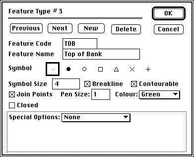
If the option Join Points is not checked, the Pen Size and Closed
options are not available. Choose Closed if a line is to be drawn
from the last point, back to the first. This is useful for displaying
a building, for example.
There are some special feature types which you can select from the
pop-up menu at the bottom of the feature dialog box. The default
condition is None. A Pegged line feature is a special feature type
that allows the profile, cross sections and setting out data to be
related to a pegged line. The pegged line should be approximately
parallel to its control line. Use Volume boundary to measure volumes
of an irregular site. Choose Cut-block for displaying cut-blocks in
the 3D view. Use Wall to help visualise features on the 3D view. Link
anchor is used automatically by HighRoad when intersections and
cul-de-sacs are created. See
Attaching a
pavement to a feature, in Chapter 7,
Typical sections for information about how to use this option in
your projects. When you select one of the items from the pop-up menu,
other conditions required for that option are forced. For example if
you choose Volume boundary then the feature has to be joined,
contourable and closed. These items are checked and made inactive so
that they can not be changed.
You can use Next and Previous to look at other features already
defined. Once you have defined the feature type, click OK, and this
feature definition will be added to the library. A new feature will
be added to the model and the list of points will be scanned in order
and any others with the same code (TOP) will be added to this
feature.
Note: It is important when doing a survey to
ensure that you pick up points along a feature in order from one end
to the other. The point numbers do not have to be consecutive, just
in order.
Once all points have been scanned, the plan will be displayed with
the features shown as you have specified.
Coding feature strings
When coding feature strings that HighRoad will insert
automatically, you should follow certain conventions. You can use up
to 12 alphabetical characters as a code for feature strings. If a
particular job has more than one feature of a particular type you
follow the alphabetical characters with a number. There is no space
between the alphabetical characters and the number. For example
following codes are valid:
Point# Code
1 TOP
2 TOE
3 TOP
4 TOE
5 DRN1
6 TOP
7 DRN1
8 TOE
9 DRN2
10 TOP
11 DRN2
These might represent the top and toe of a bank and two drains.
HighRoad would search for the following codes in the library:
TOP
TOE
DRN
Points 1, 3, 6 and 10 would be joined to form the feature TOP.
Points 2, 4, and 8 would be joined to form the feature TOE. Points 5
and 7 would be joined to form the first DRN feature, and points 9 and
11 would be joined to form the second DRN feature.
The
survey points

When HighRoad converts the text file duplicate points, or those
within 10 mm of each other, are made non-contourable. Some points are
difficult to view at a small scale because they overlap. By changing
the scale and scrolling you can view all points in the model and
examine the correctness of the information at this stage. To assist
you, various information about the points can be shown. Choose Show
Point Info... from the Plan menu. A dialog box as shown in
Figure 4-2 will appear.
Figure 4-2
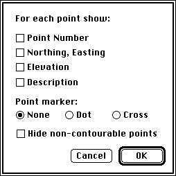
You can choose to display a point marker to show its location,
northing, easting and elevation and comments about the point. The
points can be represented by a dot, a cross or no marker at all. If
none of the items in the dialog box are selected then no information
about the points will appear on the screen. You can also choose to
hide non-contourable points. Check the box labelled Hide
non-contourable points. When non-contourable points are hidden, they
cannot be found by double-clicking on or near them.
Note: The Plan window will be blank if no
information is displayed for each point.
Editing information about a point
You can change the following information about a point: elevation,
comments and whether or not it is contourable. Double-click on the
point you wish to change. A dialog box will appear, as shown in
Figure 4-3, and you can make the relevant
changes.
Figure 4-3
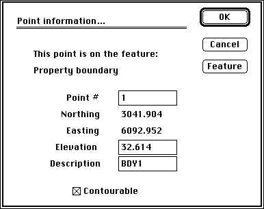
All points are marked as contourable unless they are on a
non-contourable feature or the elevation is less than -900 metres.
Before the triangulation is done you can make a point non-contourable
and these points will not be considered during the triangulation or
subsequent contouring. If you make a point not contourable, you will
not be able to click on it when forming the outside edge. The dialog
box also indicates whether a point forms part of a feature string.
You can also edit the feature information. If a feature string is
incorrect or you want to change it, double-click on any point
belonging to that feature and the dialog box (as shown in
Figure 4-3) will appear. Click Feature. A
dialog box similar to that shown in Figure
4-1 previously will appear. Alternatively you can double-click on
the feature, or click on the feature to highlight it and then choose
Get feature info... from the Edit menu. You can change the properties
of this feature using the usual editing techniques.
Defining the
perimeter

To create a terrain model of the survey data you must first create
a perimeter line enclosing the points to be contoured. Choose Join
perimeter points... from the Plan menu.
Figure 4-4
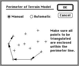
A dialog box (as shown in Figure 4-4)
will appear. You can choose to join the points manually or
automatically.
Defining the perimeter manually
Select Manual. Click OK. The cursor will be shown as a cross when
it is over the Plan window. Choose a point on the outside edge as a
starting point and click on it. Move clockwise to the next point and
click it. A line joining the two points will be drawn. Continue
clockwise around the outside edge.
As you join the points you will find that some are very close
together and it is difficult to distinguish one from the other. When
this occurs choose Zoom from the View menu and click on or near the
points you are interested. You may find the short-cuts for Zoom,
Shrink and Pan useful here. Alternatively you can scroll so that the
points in question are near the centre of the screen and then choose
a smaller scale from the View menu to enlarge the view of these
points. Try different scales as necessary to be able to correctly
join the points together.
HighRoad will not allow you to join to a non-contourable point as
part of the perimeter line. If you make a mistake, choose Undo from
the Edit menu. When you have clicked on the last point in the outside
edge, go to the point at which you first started. Click it again.
This signals to HighRoad that the outside edge is completed.
Defining the perimeter automatically
Click Automatic. The dialog box (Figure
4-5) will ask you to enter the maximum distance between points on
the perimeter and the minimum angle for triangles adjacent to the
perimeter.
HighRoad will estimate the maximum distance for you. Click
Estimate. Click OK. The estimate can be inappropriate, so you need
to check the perimeter that HighRoad defines.
Figure
4-5
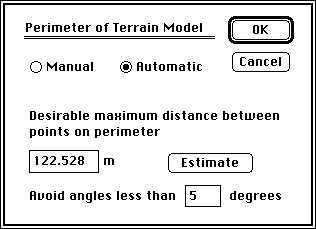
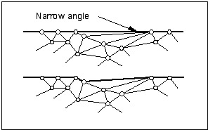
The minimum angle for triangles adjacent to the
perimeter refers to the angle between the edge line and the internal
triangle adjacent to the edge. If the angle between the edge line and
the internal triangle is less than that specified, the edge line will
follow the more concave path to avoid this narrow angle. This is
illustrated in Figure 4-6. Set the angle to
zero to consider distance only. If you wish to redo the triangulation
with a different distance or angle, choose Rejoin perimeter points...
from the Plan menu. Experiment with the different settings until you
are satisfied with the result.
Figure 4-6
The terrain
model

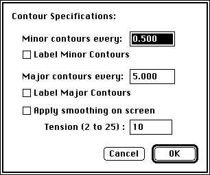
Once the outside edge is defined, HighRoad can create a terrain
model of the survey data. Choose Contours... from the Plan
menu. A dialog box will appear as shown in
Figure 4-7. You can set the contour
interval, the interval between major contours and the tension of the
contours and choose to apply smoothing on screen. HighRoad will
complete a triangulation of the data and then draw the contours on
the screen at the specified intervals and tension.
Figure 4-7
You can change the scale and scroll up and across to view the
terrain model. You can choose what information HighRoad will display
about the terrain model. You can hide or show the triangulation, the
contours and details about the points by selecting the relevant items
in the Plan menu. You can also draw the contours at different
intervals choose Contours... from the Plan menu. Choose Fit to Window
from the View menu and all the points of the terrain model will be
shown on the screen.
Making points non-contourable
Points can be made non-contourable after triangulation is done.
The triangulation is adjusted after such a change. Points on the
outside edge cannot be changed.
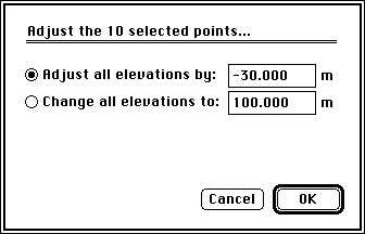
Adjusting the elevation of points
You can adjust the elevation of individual points or groups of
points. Groups of points can be selected by shift-clicking the points
-- additional points can be added to the group by shift-clicking on
them. Points in the group can be removed by shift-clicking them.
Points can also be selected by dragging a rectangle around thepoints
to be selected. The selected points will be highlighted. Choose
Adjust selected points... from Plan menu. The dialog box that appears
(see Figure 4-8)
allows you to alter all the elevations to the same value, or
change them all by the same amount.
Figure 4-8
This option is useful when working with a rock
stratum. If you know that rock in the area is generally 2 metres
below the surface, you can duplicate the DTM to create a rock stratum
at this depth. In some areas you may have more precise information
such as from test holes. In these areas of the rock DTM, select the
points in the vicinity of the test hole and adjust their elevations
to suit rock depth in this area.
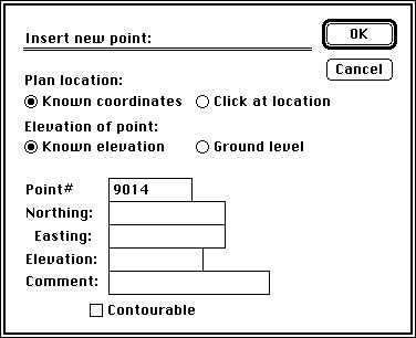
Adding new points to the terrain model
Individual points can be added to the terrain model. Choose New
terrain point... from the Plan menu and a dialog box appears as shown
in Figure 4-9. You can specify the plan
location of a point by clicking at the location of the point or by
entering its co-ordinates. The elevation of the point can be either a
known elevation or can be calculated by HighRoad to be at ground
level at that location. If you choose to have HighRoad calculate the
ground level, and the point is outside the terrain model, a notice
will be displayed and the point will not be added. Points outside the
terrain model with a known elevation will be non-contourable. The
default point number shown is the next number after the highest point
number already used. You can use any number you wish, however it is
recommended that you use a number which has not already been used in
the current project. A list of points can be read in straight from a
text file. The data must be in one of five formats:
* Point# Northing Easting Elevation [comment]
* Point# Easting Northing Elevation [comment]
* Geodimeter format
* DXF
* NTF
Figure
4-9
Points within the perimeter of the terrain model will be inserted
into the model. The points will be added into the triangle into which
they fall, or if exactly on a line between two triangles, they will
be changed to four triangles. The triangulation in the immediate
vicinity of the point will be adjusted if necessary. If there are
existing breaklines in the vicinity they will be respected. If the
points are of elevation below -900 metres they will be made
non-contourable and not added to the triangulation. If they are
outside the perimeter they will also be made non-contourable.
You can read in the additional list of points when a project is
open and the terrain model has been created. Bring a Text window to
the front. Choose Open Text File to open the list of points. Choose
Convert from the Edit menu and the points will be processed and added
to the active terrain model.
New features will be created with this process, if the new points
have comments attached. If the comments do not match codes in the
current feature library you will be asked whether to add the code to
the library (just as would happen if creating the job from the
start). If the features are breaklines, the terrain model will be
adjusted accordingly.
Additional points can be added one at a time to a terrain model
after it has been triangulated. Be sure not to put a point exactly
over an existing point or triangle edge. Points outside the limits of
the contourable model will be forced to be non-contourable. HighRoad
will retriangulate the area in which a new point is added if it is a
contourable point. Adding new points may change the shape of the
terrain and it may require further work such as the creation of a
breakline feature to ensure the model is correct.
Deleting points
You can delete points by selecting them and then choosing Clear
from the Edit menu or by pressing the delete key. To select a point
click on it. To select multiple points hold down the Shift key while
clicking on points, or drag a rectangle around the points to be
selected. If a point is on the perimeter line it cannot be deleted.
To delete such a point you must first discard the triangulation and
the perimeter line. This is done by choosing Rejoin Edge Points from
the Plan menu.
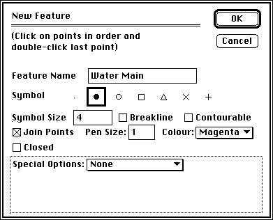
Adding feature strings manually
You can add a feature string at any time after the contours have
been formed by choosing New feature string... from the Plan menu. A
dialog box as shown in Figure 4-10 will
appear. If the option Join Points is not checked, the Pen Size
and Closed options are not available. Choose Closed if a line is to
be drawn from the last point, back to the first. This would be useful
for a building, for example. If the Breakline option is checked then
any triangles which cross the breakline will be rearranged. Once you
have selected the options you require, click OK and then click on the
points, in order, that make up the feature. You can undo any number
of points. Double-click on the last point. If the feature is a
breakline, the triangles will be redrawn so that no crossovers occur.
Figure 4-10
There are some special feature types which you can select from a
pop-up menu at the bottom of the feature dialog box. The default
condition is None. A pegged line feature is
a special feature type that allows the profile, cross sections and
setting out data to be related to a pegged line. The pegged line
should be approximately parallel to its control line. Use Volume
boundary to measure volumes of an irregular site. Choose Cut-block
for displaying cut-blocks in the 3D view. Use Wall to help visualise
features on the 3D view. When you select one of the items from the
pop-up menu, other conditions required for that option are forced.
For example if you choose Volume boundary then the feature will be
has to be joined, contourable and closed. These items are checked and
made inactive so that they can not be changed.
Editing a feature
string
If a feature string is incorrect or you want to change it,
double-click on any point belonging to that feature and the dialog
box (as shown in Figure 4-3) will appear.
Click Feature. A dialog box similar to that shown in
Figure 4-1 will appear. You can change the
properties of this feature using the usual editing techniques.
Feature strings can also be edited by clicking on the feature to
select it. (A feature that is selected is highlighted by making it
wider and patterned.) Once a feature string is selected you can edit
it. Choose Get feature info... from the Edit menu (or use the
keyboard short-cut i for Macintosh, Alt i for
Windows). A dialog box similar to that shown in
Figure 4-1 will appear. You can change the
properties of this feature using the usual editing techniques.
Alternatively, double-click on a feature and the feature dialog box
similar to that shown in Figure 4-1 will
appear. Use the usual editing techniques to change the properties of
the feature.
Faster plan redraw
You can choose whether plan redrawing will be stopped when the
mouse is clicked. Select Preferences... from the Edit menu. Check the
box labelled Stop plan redraw on mouse click. This setting will be
remembered by HighRoad. Once selected, plan redraw is stopped when
the mouse is clicked. This is useful if you are zooming in on part of
the plan. You may need to zoom in several times to get to the scale
that you want. Instead of waiting for the plan to fully redraw each
time, you can wait just long enough to see sufficient detail to know
where you are, then choose Zoom again. As you click on the View menu
the plan drawing will stop, allowing you to select Zoom again. (This
also applies if you are using the Command ( ) key on Macintosh or the Alt (
 ) key on Windows to zoom.) Be aware that the plan
view may be incomplete if the mouse button is down at any time during
plan redraw. Plan drawing does not stop under all
conditions. The first time contours are drawn they also have to
calculated. This cannot be interrupted. Subsequent redraws are much
faster (providing sufficient memory was available to store the
contours) and can be interrupted by a mouse click.
) key on Windows to zoom.) Be aware that the plan
view may be incomplete if the mouse button is down at any time during
plan redraw. Plan drawing does not stop under all
conditions. The first time contours are drawn they also have to
calculated. This cannot be interrupted. Subsequent redraws are much
faster (providing sufficient memory was available to store the
contours) and can be interrupted by a mouse click.
You can force an update of the plan view. If you interrupt the
drawing of the plan view, you may be left with a partly completed
plan. To force the Plan window to be redrawn, click on the size box
in the lower right corner. The Plan window will be redrawn
completely. You can choose not to display any mark at all for points.
Choose Show Point Info... from the Plan menu and click on None under
Point marker. This means that you do not have to wait for the dots to
be drawn for points. This speeds up redraw noticeably on slower
computers. In combination with redraw interruption this can speed
your work considerably.
You can turn off items which are not needed for the current task.
Select Hide Triangulation or Hide Features as appropriate. This will
improve redraw speed. To speed up the contour redraw, choose a larger
contour interval.
Adding another
stratum

Note: This option is available only if you have
the Extra DTM module. This module is included in HighRoad Pro and is
optional in other models.
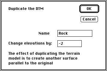
Another terrain model can be created by duplicating
the ground model, offset by a fixed height. This is useful for
modelling geological strata such as rock layers. To add this new
stratum to a project, choose Duplicate DTM from the Edit menu when
the Plan window is in front. The dialog box, as shown in
Figure 4-11, will appear.
Set the depth to the new stratum, click OK and another terrain
model representing the stratum will be created. The contours that
appear will be on the surface of the stratum. This new stratum will
appear in cross sections displayed on screen, or printed or plotted.
The names of both strata will appear in the Active menu. Choose the
active stratum (the one you want to work on) when the Plan window is
in front.
Figure 4-11
You can show or hide contours independently for each
layer. The menu item Show/Hide Contours will display the name of the
active stratum. If the stratum you wish to enter is not parallel to
the ground layer, you can change the elevation of individual points
or groups of points. Groups of points can be selected by
shift-clicking the points -- additional points can be added to the
group by clicking on them. Points in the group can be removed by
clicking them. The selected points will be highlighted. Choose Adjust
selected points... from Plan menu. The dialog box that appears (see
Figure 4-8)
allows you to alter all the elevations to the same value, or
change them all by the same amount.
Deleting the second DTM
You can delete the second stratum that you have created. The Plan
window must be the front window and the second DTM must be active.
Choose Clear from the Edit menu.
Note: Ensure that nothing is selected in the Plan
window when you choose Clear. If something is selected then it will
be deleted and not the DTM. For example if points are selected,
choosing Clear will delete the selected points.
Constructing a road or
pad

After you have completed your design, you can create a terrain
model based on the finished surface of the new design after
construction. This option is useful for calculating quantities more
precisely when you have designed building pads and roads which
overlap. It is also useful where you also need to design sewer or
stormwater pipes. Design the road control line first, then construct
the road (or pad). Choose Construct <Control line name>
from the Plan menu. Now the terrain model shows the ground surface
after construction. This would be useful for the design of pipes or
intersecting roads or pads.
Note: Construct a road or pad only after you are
sure of its position. Before you do this duplicate your
original file otherwise you will lose it. Make sure the control line
and its cross sections all remain totally within the terrain model
before constructing.
When you construct the building pad the triangulation within the
perimeter of the pad will change entirely. Some changes may also
occur to triangles which adjoin the pad. The new triangles are formed
according to the Voronoi diagram (see
24-1) and to suit new breaklines created
along the edge of the pad and along the edges of links that make up
the batter slopes. Occasionally, especially at corners, such a
triangulation may not be ideal. You should examine the triangulation
near the corners to verify that the triangle edges radiate from the
corner. If not you may wish to insert additional breaklines radiating
from the corner.
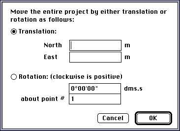
Transformations

You can change the co-ordinates of all points in a project by
translation or rotation. When the Plan window is active, and no
points are selected, choose Offset Entire Project... from the Plan
menu. You will be presented with the dialog box shown in
Figure 4-12.
Note: Keep in mind when rotating a project that
all co-ordinates are rounded to the nearest millimetre. Multiple
rotations can result in compounding of rounding errors of up to 1mm
for each rotation. This can mean if you rotate a project and then
rotate it back by the same angle, some co-ordinates may change by 1
or 2 millimetres. For most purposes this is far more precise by one
or more orders of magnitude than the original data and so is of no
practical consequence.
Figure 4-12
| Previous |
Next |
Copyright 2001 Creative Engineering