This chapter shows you how to display cross sections on the screen and how to view these sections in different ways.
![]()
The Cross Section Plot window allows you to view cross sections at different scales and in different formats. The vertical and horizontal scroll bars assist you to view different parts of a cross section. You can also use the Zoom, Shrink and Pan commands (and short cuts) to view different parts of the cross section. Cross sections are interpolated using the triangulation. The reliability of the cross sections is therefore dependent on how well the triangulation represents the natural surface. (For more details about the triangulation, see Triangulation, Chapter 24)
Opening the Cross Section Plot window
It is useful to view the cross sections when designing a profile. HighRoad allows you to open the Cross Section Plot window from within the Profile window. Drag the pointer to the chainage at which you wish to see the cross section. As you drag the pointer, the cursor will change to a dotted vertical line and the chainage will be displayed against this line. (If the Plan view is visible, a line will appear, showing the location and width of this section.) Release the mouse button. The Cross Section Plot window will be opened (or, if it has previously been opened, will move to the front) and display the cross section at the chainage you have selected. You can also open the Cross Section Plot window by choosing Cross section plot... from the Window menu.
Note: If you have not designed a typical section for the location requested, the nearest location for which a typical section applies will be displayed. If you want to display a cross section of the natural surface only, you can specify a chainage range for the default, blank typical section.
If you display a cross section where there is no design profile its control point will be at ground level. This is useful for road widening where you may want to match the existing pavement levels at the centre, and the new work is attached to the edges, such as in shoulder widening.
![]() Displaying cross sections at
different scales.
Displaying cross sections at
different scales.
You can change the scale of a displayed cross section by choosing the required scale from the View menu. The cross section is plotted at a natural scale (that is, the horizontal and vertical scales are equal). The scale can also be changed by a factor of two by using the Zoom and Shrink commands in the View menu.
Showing offsets and levels.
You can choose to display (and print or plot) only a line diagram of the finished surface and the natural surface or you can show the offsets and levels of the natural and finished surfaces. You can also show a datum line on the cross sections. Choose Cross section plot... from the Window menu. Choose Layout... from the Section menu. A dialog box will appear as shown in Figure 10-1. Use the check boxes to select the options you require.
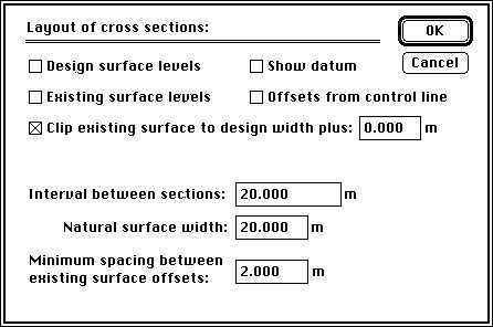
The option Clip existing surface is useful to minimise the space taken up on plotted and printed drawings by showing only the natural surface within the design width. That is, any part of the natural surface outside the limits of the batter points is removed. Space savings can be worthwhile when the width of the natural surface is significantly wider than the width of the finished surface.
Interval between sections
This distance is used when you wish to display cross sections in sequence, produce drawings of cross sections, calculate quantities or display chainages on the Plan view.
Natural surface width
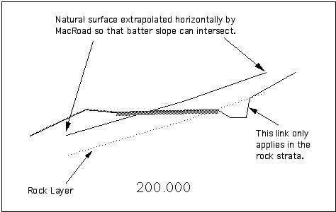
This option specifies the width of the natural surface cross section which will be extracted from the terrain model. You should make sure that this width is sufficiently wide for the cross sections. If it is not wide enough the batter may be incorrect and therefore the quantities could be incorrect. An example of a cross section where the natural surface width is too narrow is shown in Figure 10-2. For speed of operation, you should set this width to the minimum appropriate width for the project.
Note: Beware of the using a wide cross section width on a terrain model which has a winding outside edge line. If the cross section line is wide enough to run off the edge and then back on again the natural surface plot will not be correct.
Minimum spacing between existing surface offsets
This option allows you to set the minimum distance between offsets displayed on the cross section. HighRoad calculates the natural surface level wherever the cross section crosses a triangle edge in the terrain model. In some cases this may result in many natural surface levels displayed very close together on the cross section. This clutter can be avoided by appropriately setting the minimum distance between offsets displayed on the cross section.