|Creative Engineering
home page|
|Table of contents |
Learning HighRoad |
Using HighRoad|
Reference|
| Previous |
Next |
Chapter 9
Transitions
This chapter shows you how to calculate and edit
superelevation and curve transitions based on design speed.
Superelevation
calculation method

HighRoad allows you to choose different methods of calculating the
maximum superelevation and the length of superelevation runout and
plan transitions.
Maximum superelevation
Superelevation is used to minimise the effect of centripetal force
on driver/passenger comfort and maximise the adhesion of the tyre to
the road when cornering. This is done by tilting the pavement towards
the centre of the curve so that centripetal forces are somewhat
offset by the pavement crossfall.
Road authorities adopt various methods of calculating the amount
of superelevation required to achieve comfort and cornering ability
for the traffic that is travelling at design speed. Some authorities
use an empirically derived table of maximum friction demand for
various design speeds to choose the amount of superelevation needed.
It has been found that drivers/passengers are more tolerant of higher
friction demand when travelling at low speed. As the speed increases
their tolerance of friction demand decreases. The acceptable values
fall in a fairly narrow range, and some authorities have adopted a
fixed value for friction.
HighRoad allows you to use an approriate superelevation formula
and to edit the friction table if necessary.
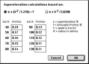
To select the formula or edit the friction table, choose
Transitions... from the Window menu. Choose Superelevation... from
the Transitions menu. A dialog box as shown in
Figure 9-1 will appear. Choose the formula
you wish to use. The formula on the left explicity includes a
variable for friction demand. This is taken from the table depending
on the design speed. The formula on the right allows for friction
demand implicity and the friction table is not used. The new settings
will be saved with the project and the last used set of friction
values and formula will be saved with HighRoad.
Figure 9-1
Application of
superelevation
 Superelevation can be included in
your road design in the following ways:
Superelevation can be included in
your road design in the following ways:
* automatically
* automatically with manual override of certain parameters
* manually by adding extra typical sections.
Automatic superelevation
Before HighRoad can automatically calculate superelevation you
need to have designed a horizontal alignment, a typical section and a
profile for your project. Choose Transitions... from the Window menu.
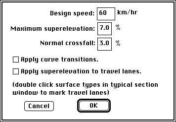
Choose Options... from the Transitions menu. A window will appear as
shown in Figure 9-2.
The first time this dialog box appears for a new road, the design
speed is set to 60 kph, the maximum superelevation is 7% and the
normal crossfall is 3%. The check boxes for the other items are
blank. Change these settings as required. Make sure that the normal
crossfall specified matches the crossfall you have shown in the
typical sections for the travel lanes. HighRoad does not check this.
Enter the design speed of the road and the maximum superelevation
allowed. Click the appropriate box to apply superelevation to travel
lanes. (For information about how to specify travel lanes see page
7-10.)
Figure 9-2

HighRoad will calculate the amount of superelevation and the
location of superelevation transitions when you click OK. If any of
the straights between the curves are too short to allow sufficient
length for the superelevation transition, or the required
superelevation is greater than the maximum you specify, a warning
will be displayed. If you change the horizontal alignment, the
superelevation will be recalculated.
Note: Although HighRoad will calculate
satisfactory superelevation transitions for a given curve under most
circumstances, the values calculated should be checked by an
experienced road designer. This is essential to ensure that the
superelevation is appropriate for the local conditions and
practice. It is particularly important to check the values
when HighRoad displays a warning on the screen.
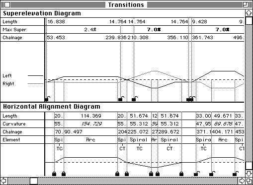
Editing values for superelevation
Once the values have been calculated by HighRoad, you may alter
any of the chainages or the superelevation for any curve. These
values will be shown in the Transitions window (choose Transitions...
from the Window menu) as shown in Figure
9-3.
The chainages or lengths can be adjusted by typing in new data or
by dragging the ordinate. You can drag the ordinates when the mouse
is over the line. The cursor will change to an ordinate icon ( ) when over the ordinate that can be moved.
The superelevation transitions can be locked in the position you
require by clicking the lock icon at the bottom of the ordinate. The
cursor will change to a key icon ( ) when it is in position to lock or unlock the
transition ordinate. When the transition is locked, the lock icon
(
) when it is in position to lock or unlock the
transition ordinate. When the transition is locked, the lock icon
( ) will appear at the bottom of the
ordinate. When it is unlocked, the icon will appear unlocked (
) will appear at the bottom of the
ordinate. When it is unlocked, the icon will appear unlocked ( ).
).
Figure
9-3
Once you lock any of these values they will be fixed
and not recalculated by HighRoad. Any values which are not fixed will
be recalculated when the file is reopened or there is a change in :
* horizontal alignment
* design speed
* maximum superelevation.
Note: When a transition is locked, its length is
locked in relation to the curve it is attached to. If the curve is
changed the location of the transition will be moved to match the
curve.
Superelevation values or transition lengths will appear bold (and
red on a colour screen) when they are less than required for the
design speed you have specified.
Note: The values calculated by HighRoad will not
be rounded up or down as is the case with guidelines set down by most
road authorities. You may wish to adjust the chainages shown so that
they conform to the practice of the road authority under whose
jurisdiction the work falls.
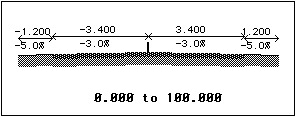
Manual superelevation
Superelevation can also be included in the road design by adding
extra typical sections with amended crossfall. Begin by drawing the
typical section for the start of the road, as shown in
Figure 9-4. The chainage range is from the
start chainage to the point where the superelevation starts.
Figure 9-4
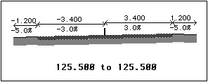
The first step is to bring the outer lane up to the same crossfall
(3%) as the inner lane (see Figure 9-5). The
chainage range will be zero length, that is, if it occurs at chainage
125.500, specify its chainage range as 125.500 to 125.500.
HighRoad will interpolate the crossfall between these two typical
sections, that is, between chainages 100.000 and 125.500.
Figure 9-5
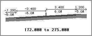
The next step is to change the crossfall over the full width of
the travel lanes until full superelevation (6%) is achieved (see
Figure 9-6). From this point (chainage
172.000), the shape of the typical section remains constant until the
end of the curve (chainage 275.000) where the superelevation begins
to change back to normal crossfall. HighRoad will interpolate between
typical sections.
Figure 9-6
Plan
transition

A curve inserted to link the straight or tangent section of a road
with the circular arc is known as a plan transition curve. Its radius
reduces from infinity at the end of the straight to that of the
circular arc at the beginning of the arc. Forms of curve which
approximate these requirements include the cubic parabola, the
lemniscate, and the clothoid (alternatively referred to as the Euler
spiral or Cornu spiral). HighRoad uses the cubic parabola or the
clothoid to calculate plan transition curves.
Cubic parabola or clothoid
You can choose whether to use the clothoid or cubic parabola form
of transition. There is little practical difference between a
clothoid or cubic parabola. However in HighRoad there is a difference
in how the cross sections and other data is presented. Choose
Preferences... from the Edit menu to choose to use either the cubic
parabola or the clothoid for plan transition curves.
Note: It is recommended that you select the
preferred transition curve when you start work on the project.
Changing the type of curve used in the design may produce unexpected
results.
The cubic parabola was most often used for manual calculation of
transition curves. Since the advent of computers, clothoid spirals
have come into more common use. Clothoid spirals are mathematically
more complex and tedious to calculate by hand.
HighRoad uses cubic parabola transitions in a similar manner to a
manual implementation of cubic parabola transitions. That is, the
nominal road centre line is made up of straights and circular arcs
only. This centre line would be pegged in the field. The true road
centre line would deviate from this line around the curves. Cross
sections around the curves show a shift or offset from the nominal
centre line to the true centre line. The shift varies from zero at
the start of the plan transition to a maximum at the end of the
transition where it meets the circular arc. HighRoad will calculate
the start and end points of the plan transition and also an
appropriate value for the shift. Chainages are measured along the
nominal centre line along straights and circular arcs. The curved
sections of such a road are easy to peg in the field because all the
pegs are on a circular arc.
When clothoid spirals are used there is only one centre line the
true centre line. This follows straights, spirals and circular arcs.
Chainage is measured along this line. Because the control line
follows the path of road centre line, there is no shift shown for
cross sections on curves. The setting out information that HighRoad
provides is on the true road centre line.
The actual location of the road will be very similar whichever
method is used. It is a matter of personal preference which method
you choose, having due regard to the intended method of setting out
in the field.
Calculating plan transitions
Before HighRoad can automatically calculate a plan transition for
each curve you need to have created a horizontal alignment, a typical
section and a profile. HighRoad also requires the design speed of the
road and the maximum superelevation allowed. Choose Transitions...
from the Window menu. Choose Options... from the Transitions menu. A
dialog box will appear as shown in Figure
9-7.
Figure 9-7
The first time this dialog box appears for a new road, the design
speed is set to 60 kph, the maximum superelevation is 7% and the
normal crossfall is 3%. The check boxes for the other items are
blank. Change these settings as required. Type in the design speed of
the road, the maximum superelevation allowed and the normal
crossfall. Click the appropriate box to apply curve transitions.
HighRoad will calculate the required superelevation, the required
shift and the appropriate transition length when you display the plan
view or a cross section. If any of the straights between the curves
are too short to allow sufficient length for the plan transition, or
the curve radius is too small and friction demand is excessive, a
warning will be displayed.
Note: Although HighRoad will calculate a
satisfactory transition location and shift for a given curve under
most circumstances, the values calculated should be checked by an
experienced road designer. This is essential to ensure that the
transition curve is appropriate for the local conditions and
practice. It is particularly important to check the values when
HighRoad displays a warning on the screen.
Nominating values for curve transitions
Once the values have been calculated by HighRoad, you may alter
any of the chainages, the shift or the superelevation for any curve.
These values will be shown in the Transitions window (choose
Transitions... from the Window menu) as shown in
Figure 9-8.
You can set the chainages for the start and finish of the spiral
and the start and finish of the circular arc on shift. The chainages
or lengths can be adjusted by typing in new data or by dragging the
ordinate. You can drag the ordinates when the mouse is over the line.
The cursor will change to an ordinate icon ( ) when over the ordinate that can be moved. The
plan transitions can be locked in the position you require by
clicking the lock icon at the bottom of the ordinate. The cursor will
change to a key icon (
) when over the ordinate that can be moved. The
plan transitions can be locked in the position you require by
clicking the lock icon at the bottom of the ordinate. The cursor will
change to a key icon ( ) when it is in position to
lock or unlock the transition ordinate. When the transition is
locked, the lock icon (
) when it is in position to
lock or unlock the transition ordinate. When the transition is
locked, the lock icon ( ) will appear at the
bottom of the ordinate. When it is unlocked, the icon will appear
unlocked (
) will appear at the
bottom of the ordinate. When it is unlocked, the icon will appear
unlocked ( ). Once you lock any of these values
they will be fixed and not recalculated by HighRoad. Any values which
are not fixed will be recalculated when the file is reopened or there
is a change in :
). Once you lock any of these values
they will be fixed and not recalculated by HighRoad. Any values which
are not fixed will be recalculated when the file is reopened or there
is a change in :
* horizontal alignment
* design speed
* maximum superelevation.
Figure 9-8

Note: It is recommended that you
select the preferred transition curve when you start work on the
project. Changing the type of curve used in the design may produce
unexpected results.
The length of transition will appear bold (and red on a colour
screen) if it is below standard for the design speed you have
specified.
Note: The values calculated by HighRoad will not
be rounded up or down as is the case with guidelines set down by most
road authorities. You may wish to adjust the chainages shown so that
it conforms to the practice of the road authority under whose
jurisdiction the work falls.
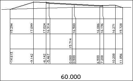
Cubic parabola effect on cross sections
If a plan transition of greater than 250 mm is included, the
typical section will be shifted to the left or right of the pegged
centre line. If the maximum shift is less than 250 mm the shift is
not applied at all. An example of a cross section with a
superelevation and shift applied is shown in
Figure 9-9. In this example the shift is 533
mm to the right. Superelevation has been applied to the travel lanes.
Figure
9-9
| Previous |
Next |