Figure
6-1
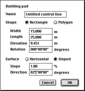
Select Building pad, name the building pad, enter the width and
length of the pad and click OK. The name will appear in the Active
menu.
Note: When you design a building pad the first
step is to create a rectangular shape. You can then alter this to the
shape that you require. The rockfall option is available as part of
the optional Rockfall Simulation module. If you need to protect
facilities against rockfall risk this module will help you design the
protection measures. Contact Creative Engineering or your distributor
for more information
The cursor will appear as a cross on the Plan view. You can now
position the building pad on the terrain. Hold the mouse button down.
The building pad outline will appear to scale on the Plan view. Drag
it to the position that you require. When you release the mouse
button the pad will be drawn complete with cut and fill batter slopes
as appropriate.
Note: HighRoad inserts a 1 metre radius curve at
each vertex so that batter slopes continue smoothly around the
corner.
The elevation of the building pad will be the same as the ground
level at the location where you first click the mouse button. The pad
will be initially oriented with its length up the screen and its
width across the screen.
Adjusting the pad size and elevation
Double-click the building pad to adjust its size and elevation.
(The cursor changes to a hand shape when over the active building
pad). A dialog box as shown in Figure
6-2 will appear. You can change the width, length
and elevation of the pad, set the rotation and change the building
pad to a polygon.
Changing the slope of the building pad
The building pad you create is initially horizontal. If you want
to make a sloped top surface, double click the building pad to bring
up the dialogue box as shown in Figure 6-2
and select Sloped. You can specify the slope in % with positive being
a slope up, and negative being a slope down. The direction of the
slope can be in degrees or grads, whatever is currently chosen as
your preference for angles.
Figure 6-2
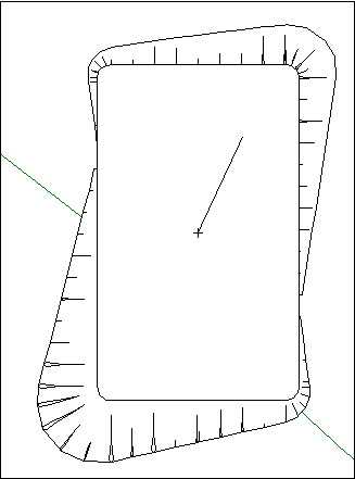
When a pad has a top slope it is drawn with a cross and a line
showing the direction of slope, as in Figure 6-3. To change the
slope, or the direction of slope, double-click the pad to show the
dialog box again. (The pad needs to be the active control line, that
is currently selected in the Active menu). Both rectangular and
polygonal pads can have a sloped top surface.
Shaping the building
pad
The building pad is a rectangular shape at first. Select Polygon
from the dialog box (see Figure 6-2) if you require a shape that is not
rectangular.
You can move the IPs (vertices) of the building pad to change it
to an irregular quadrilateral shape. Move the pointer to the IP you
want to adjust and it will change to a four pointed arrow ( ). Drag the IP to the new location. HighRoad will
redraw the new view of the plan.
). Drag the IP to the new location. HighRoad will
redraw the new view of the plan.
Note: Do not drag any IP outside the terrain
model, or locate it so that the edge of the pad crosses outside the
terrain model.
Figure 6-3
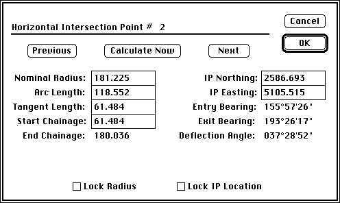
You can also precisely specify the location of the IP and the
details of the curve data. Double-click on the IP when the cursor is
a four pointed arrow ( ). The dialog box shown in
Figure 6-4 will appear on the screen.
). The dialog box shown in
Figure 6-4 will appear on the screen.
The corners of a pad are given a radius of 1m when they are first
created. Change the position of the IP or the elements of the curve
using the usual editing techniques. Click Calculate Now to show the
effect of any change on the other curve data. If you make a change
and then move to another field, the curve data will be recalculated.
Click Previous and Next to view the previous or next IP along the
edge of the pad.
Figure 6-4
You can also change the form of the building pad by adding or
deleting IPs. Insert IP... and Delete IP... are available in the Plan
menu when there are at least 3 IPs. (You can delete IPs until the pad
is triangular in shape). To insert an IP into a building pad find the
number of the IP (by double-clicking on it) after which you wish to
insert an extra IP. Choose Insert IP... and a dialog box which asks
for this number will appear. The extra IP will be inserted half way
between the IP you nominated and the next IP. You can then drag it to
its correct location, or relocate it by double-clicking it and
editing the values shown in the dialog box. To delete an IP, choose
Delete IP... The cursor will change to an X shape. Position the
cursor over the IP to be deleted and click. The IP will be deleted.
Rotating the building pad
The rotation of the pad is measured clockwise from the original
orientation. For a rectangular pad a rotation of 90 degrees has a
similar effect to swapping the length and width dimensions.
In the case of a polygonal pad, selection of a suitable rotation
can be used to make editing of the individual legs of the pad easier.
Consider an L shaped pad. If the L shape is designed with a rotation
of zero and the legs aligned to the cardinal directions it is easy to
set the legs to the correct length. Once the correct shape has been
set up, the pad can be rotated to its correct orientation. As the
design progresses you may decide that the pad shape needs to be
adjusted. It may be easier to do this by first setting the rotation
back to zero, amending the pad shape, and then setting the
orientation to the correct value.
Viewing the building
pad

You can select what information HighRoad will display about the
building pad in the Plan view. Select Show <Building pad
name> details... from the Plan menu. A dialog box with the
name of the pad, as shown in Figure 6-5,
will appear.
Figure 6-5
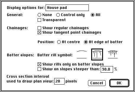
You can choose to show no details, control line only or the whole
pad. The transparent option and the batter rill symbols are only
available when All is selected. If All is selected and the building
pad runs off the edge of the terrain model only the control line will
be shown.
HighRoad inserts a 1 metre radius curve at all the corners so that
the batter slopes follow smoothly around the corners. When HighRoad
draws the Plan view it calculates the batter slopes at the Cross
section interval set by you (see Figure
6-5). The cross section interval used to draw batter slopes is
set to a number of pixels on screen. At the corners this interval is
adjusted so sufficient detail is available.
If you require a different radius at the corners you must select
Polygon from the dialog box (see Figure
6-2). Double-click on the vertex (as described in
Shaping the building pad, page
6-3) to make this change.
Redrawing the plan
Redrawing the plan view of the building pad after scrolling may
take some time. The speed of drawing is influenced by the size of the
straight segments which are drawn to represent curved lines. With
long segments, the speed of drawing is faster but the drawing appears
as a series of straights rather than as a smooth curve. You can
change the segment length by typing in the required distance between
cross sections in pixels. Selection of a larger distance between
cross sections (for example, 40 pixels) will speed up the redraw
considerably but may not be suitable for detailed work or when
printing. You can also choose not to display any mark at all for
points. This means that you do not have to wait for the dots to be
drawn for points. This speeds up redraw noticeably on slower
computers. In combination with redraw interruption (as discussed
below) this can speed up your work considerably.
HighRoad allows you to choose whether plan redrawing will be
stopped when the mouse is clicked. Select Preferences... from the
Edit menu. Check the box labelled Stop plan redraw on mouse click.
This setting will be remembered by HighRoad.
Once selected, plan redraw is stopped when the mouse is clicked.
This is useful if you are zooming in on part of the plan. You may
need to zoom in several times to get to the scale that you want.
Instead of waiting for the plan to fully redraw each time, you can
wait just long enough to see sufficient detail to know where you are,
then choose Zoom again. As you click on the View menu the plan
drawing will stop, allowing you to select Zoom again. (This also
applies if you are using the Command ( ) key on Macintosh or the Alt (
 ) key on Windows to zoom.) Be aware that the plan
view may be incomplete if the mouse button is down at any time during
plan redraw.
) key on Windows to zoom.) Be aware that the plan
view may be incomplete if the mouse button is down at any time during
plan redraw.
Plan drawing does not stop under all conditions. The first time
contours are drawn they also have to calculated. This cannot be
interrupted. Subsequent redraws are much faster (providing sufficient
memory was available to store the contours) and can be interrupted by
a mouse click. You can also force an update of the plan view. If you
interrupt the drawing of the plan view, you may be left with a partly
completed plan. To force the Plan window to be redrawn, click on the
size box in the lower right corner. The Plan window will be redrawn
completely.
Multiple building pads
Note: This option is available only if you are
using HighRoad Plus, HighRoad Pro or have purchased the license to
use the Extra control lines module.
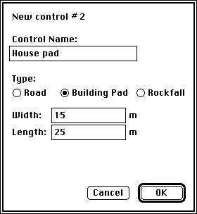
You can add up to 100 control lines in any project. Select New
control line... from the Plan menu. A dialog box (as shown in
Figure 6-1) which allows you to name the
building pad, will appear. Each time you add another building pad its
name will also appear in the Active menu. The current building pad
(the one on which you are working) has a tick against it in the
Active menu and all views of the building pad (Plan, Profile, Typical
sections etc.) show information relating to that pad. The details
displayed about each building pad in the Plan view will depend on
what you have selected for that building pad. Choose Show
<Building pad name> details... from the Plan menu. A
dialog box with the name of the building pad, as shown in
Figure 6-5, will appear. Choose the details
to be shown for that building pad.
Note: At present no account is taken of
intersecting building pads when calculating quantities or batter
slopes unless all building pads which intersect the current one have
been constructed. See
Constructing a road or
pad, Chapter 4.
| Previous |
Next |