|Creative Engineering
home page|
|Table of contents |
Learning HighRoad |
Using HighRoad |
Reference|
| Previous |
Next |
Chapter 23
Troubleshooting
You may occasionally encounter difficulties when you
are using HighRoad. This chapter offers some guidelines for
diagnosing and resolving such difficulties
Triangulation
problems

You may occasionally encounter difficulties when creating a
trinagulation from a set of points. It is helpful to understand the
steps that HighRoad goes through when creating a triangulation and
the contouring a project. The three main steps are:
* create the triangulation
* check and adjust triangles to match breaklines
* Thread contours through triangles.
Triangulation can sometimes fail if points are very close
together. HighRoad attemps to counter this problem by checking for
points closer than 10mm and making one point of a close pair
non-contourable. On occasions this may not be close enough. You can
sometimes see a failed triangulation as one point with many radiating
lines drawn to other points to its north. If you can identify such a
point, make it non-contourable to begin with. After the triangulation
has been done, make it contourable again.
This problem may not be apparent until breaklines or contours are
attempted. If HighRoad locks up during creation of breaklines, try
turning off any breaklines until after the triangulation is done. If
HighRoad locks up during creation of contours try setting the contour
interval to a large distance that avoids having any contours at all
on the terrain in question. You can sometimes then identify a problem
with the triangulation. For example, if you project has a range of
elevations for 300 to 700, set the contour interval at 1000 for both
major and minor contours. Then display the triangles and examine them
for problem areas. If you can identify a problem area, or point, set
one or more points in that area to non-contourable and try again.
Plotting problems

The message 'Please insert the next sheet in the plotter...'
constantly appears on the screen.
When plotting cross sections this may be because a cross section
is too wide or tall for the sheet. HighRoad adds cross sections one
by one to the sheet until it reaches a stage when no more cross
sections will fit. At this point it will arrange the cross sections
that fit on the sheet, plot them, and then ask for the next sheet to
be inserted. If the first cross section to go on a sheet will not
fit, no cross sections need to be plotted, so HighRoad requests the
next sheet to be inserted. This will continue ad infinitum. You will
have to cancel the plotting and investigate why the cross sections do
not fit.
The cross sections may be too large for a number of reasons:
1. The natural surface may be too wide or high to fit on the
sheet. If this is the problem use the "Clip to Design" option to make
the cross section plot narrower.
2. The finished surface plot may be too wide or high to fit on the
sheet. If so use a smaller scale. To check for this, display the
cross sections on the screen and check those in the chainage range
where the problem was encountered.
Cross
section difficulties

Cross section disappears off the top of the screen
This may occur if there is an incorrect natural surface or
finished surface elevation of zero. Choose Layout... from the Section
menu and choose to display offsets, design levels, and natural
surface levels. Redisplay the cross section and check whether there
is an elevation of zero in either the finished surface or natural
surface data.
If the zero elevation is in the natural surface data, correct it
by altering the terrain model.
Batter slope missing from plot
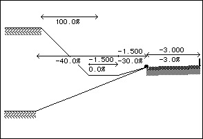
Consider the example in Figure 23-1. The
intention is to have either:
* In a cutting, from the split point, a slope of 30%
down to flat drain 1.500 metres wide, and then a batter slope of 100%
up to the natural surface.
* On a fill, from the split point, a slope down at 40% to the
natural surface.
Figure 23-1
HighRoad attempts to determine the cross section shape
in the following manner. The shape of the cross section from the
centre line out to the split point is fixed. From the split point,
HighRoad follows down the slope of 30% to the drain, across the
bottom of the drain, and then attempts to intersect the batter slope
with the natural surface. If an intersection is possible, this
configuration is adopted, and the cross section is plotted.
If the natural surface could not be intersected (that is, it is
below the outer edge of the drain), HighRoad returns to the split
point and searches again for a batter slope. In this case it attempts
to intersect a 40% downward sloping batter with the natural surface.
If this slope intersects the natural surface, the cross section is
plotted.
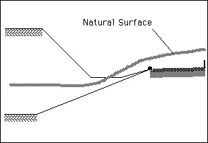
If the natural surface could not be intersected (that is, the
natural surface is above the split point), HighRoad goes back to the
split point searches again for a batter slope. In this example there
are no more batter slopes, so HighRoad cannot insert a batter slope.
This situation can arise if the natural surface is of such a shape
that it passes above the split point, and below the outer edge of the
drain as shown in Figure 23-2.
Figure 23-2
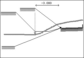
In order to prevent this problem from occurring, you
can add another batter of fixed offset. Double-click the batter tool
and select the fixed offset option. Draw the batter with an offset
equal to the outer edge of the drain (that is, 3.000 metres). Now
when HighRoad searches for the batter, it will always be able to find
the fixed offset batter (as in Figure
23-3).
Whenever you use a fixed offset batter in combination with other
batter shapes, always add the fixed offset batter last, because
HighRoad can always intersect it with the natural surface.
Figure 23-3
Plan
view problems
 Pavement or other edges cross
over
Pavement or other edges cross
over
Batters extend away from the road a greater distance than
expected
Figure 23-4
Either of these problems usually indicates that
links have been added to consecutive typical
sections in a different order. When HighRoad interpolates between
typical sections, each link is connected to its matching number in
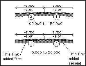
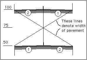
the next typical section. Consider a typical section drawn in the
order left pavement first, and right pavement second, both with 3.500
width as shown in Figure 23-4.
If the next typical section is drawn with the right pavement as
the first link and the left pavement as the second link, the pavement
edges will cross over the centre line. HighRoad will interpolate
between link #1 in the first section and link #1 in the second
section. The offset to the edge of this link will change from -3.500
at the end of the first section to +3.500 at the start of the second
section. See Figure 23-5.
Figure 23-5
It would be unusual for this to happen if the typical sections are
created by choosing Duplicate Typical Section from the Edit menu.
This makes a copy of last section, which means that its links are
exactly the same. If some links are removed (using Undo) and replaced
in a different order, or a typical section pasted from another job,
then this problem may occur.
If batters extend a long distance from the edge of the road, it
may be because a cut and fill batter in subsequent sections are in
different order. If so then the cut batter of the first section (with
a slope of +30% for example) is interpolated with a fill batter in
the next section (with a slope of -30%). The batter slope will vary
from +30% to -30% between typical sections. Near the half way point,
the slope will be close to horizontal, resulting in the batter
extending a long distance before it intersects with the natural
surface.
To correct both these examples, copy the first section, paste over
the second (or vice versa) to ensure that the links are in the
correct order and then make the appropriate alterations. If you do
this be sure to correct the chainage range after
pasting.
| Previous |
Next |