Preparing for a
cul-de-sac

In order to create a cul-de-sac you must first design the
cul-de-sac road. This should be done completely, even if just in a
trial form. It should have a horizontal alignment, a profile, and a
typical section.
The cul-de-sac will be automatically attached to the end of this
road. The typical section of the cul-de-sac will be based on the
typical section of the road you have designed. Similarly the
cul-de-sac grading will be derived from the grading of the road. The
road that you wish to attach a cul-de-sac to should be active when
you are ready to create the cul-de-sac. Choose the road from the
Active menu.
Creating a
cul-de-sac

Choose Place Cul-de-sac on <Road name>... from the Plan
menu. A dialog box as shown in Figure 11-1
will appear.
This shows in a diagrammatic form the shape of a cul-de-sac,
together with critical chainages along the control line of the road.
The Cul-de-sac calculator will create a cul-de-sac using the
following default dimensions:
* cul-de-sac radius 8.0 m
* left and right radius 7.5 m
* offset from the road control line 0
Figure
11-1
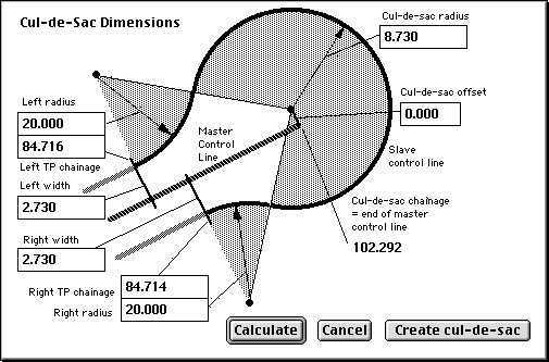
The left and right width are initially set at the width of the
first link of the typical section on the left and right of the road.
If you have a kerb on the edge of this link, the control line of the
cul-de-sac will follow along the inner reference line of the kerb.
This allows the cul-de-sac kerb to be graded to suit the drainage
design of the cul-de-sac, rather than the grade of the road control
line.
Changing the cul-de-sac dimensions
You can change the following parameters of the cul-de-sac shape:
* the cul-de-sac radius
* the left and right radius
* the left and right width
* the offset from the road control line.
Make the changes as appropriate. As you Tab to the next field,
press Return or click Calculate any dependent parameters will be
updated to suit the new dimensions. You can instantly see the result
of your changes.
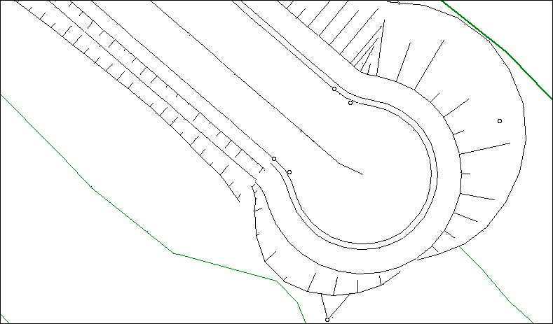
Click Create cul-de-sac and HighRoad will create the cul-de-sac
for you. Figure 11-2 is an example. The
elements of the cul-de-sac include a new control line to represent
the line of the kerb around the cul-de-sac, a series of typical
sections and a profile.
Adjusting a
cul-de-sac

The cul-de-sac control line should be active when you want to
adjust the cul-de-sac. Double-click the cul-de-sac to adjust its
dimensions. (The cursor changes to a hand shape when over the active
cul-de-sac). A dialog box as shown in Figure
11-1 will appear. You can now adjust the dimensions of the cul-de
sac.
You can also drag the cul-de-sac. When you do so the last IP of
the road will follow. Conversely if you make any changes to the road
control line, the cul-de-sac will automatically follow, both in plan
and in vertical alignment.
Figure
11-2
Control line
The cul-de-sac control line is created in relation to the end of
the control line of the road. The start of the cul-de-sac control
line is the left tangent point (TP) chainage as shown in the
Cul-de-sac calculator (Figure 11-1). The
left TP chainage is calculated based on the radius of the cul-de-sac,
the offset, the width of the left pavement, the left radius and the
curvature, if any, of the road control line. The cul-de-sac control
line initially follows around the edge of the first link on the left
side of the road. If you have a kerb on the edge of this link, the
control line will follow along the inner reference line of the kerb.
Around the head of the cul-de-sac the control line follows the arc of
a circle matching the head radius. The end of the cul-de-sac control
line connects to the first link on the right side of the road. This
allows the cul-de-sac kerb to be graded to suit the drainage design
of the cul-de-sac, rather than the grade of the control line of the
road.
Profile
The profile of the cul-de-sac is derived from the profile along
the cul-de-sac road. The critical points are the level and grade of
the road at the cross-section where the cul-de-sac starts and
finishes, and the level at the end of the road.
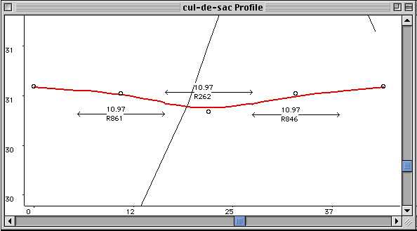
Figure 11-3 is an example of a grading
on a cul-de-sac. There are five vertical intersection points (IPs) on
this gradeline, represented by a circle ( ).
).
Note: A double circle indicates that this IP is
synchronised with another control line.
The first and last (the cul-de-sac start and finish) are
controlled by the level of the cul-de-sac road. The second and fourth
are positioned at the quarter points, and given an elevation to
produce the grade required at each end. The third (middle) IP is
positioned at the halfway point, and its elevation is derived from
the elevation at the end of the cul-de-sac road and the shape of the
typical section at the head of the cul-de-sac. This creates a
cul-de-sac shape with a lowpoint or highpoint halfway around the
head.
The start and finish of the grading shown in
Figure 11-3 have the same elevation
because, in this example, the typical section of the cul-de-sac road
is symmetrical. They also have the same grade, although in opposite
directions. Both match the elevation and grade on the cul-de-sac
road. (The cul-de-sac road has a downward grade where the cul-de-sac
starts. So the start of the cul-de-sac gradeline is downward at the
same slope.) The third IP is calculated from the elevation at the
centre of the cul-de-sac and the slope and offset to the mid point of
the control line.
Figure
11-3
The grading of the cul-de-sac remains linked to the grading of the
road. If you change the grading of the road, then the grading of the
cul-de-sac will change to suit.
Note: The recalculation of the cul-de-sac is
triggered by moving a horizontal IP of the road, a vertical IP of the
road or changing a typical section of the road..
Typical Sections
Three typical sections are created by HighRoad in order to create
the cul-de-sac. A typical section which forms a cul-de-sac is
significantly different to a normal road typical section. The typical
section looks similar to half a road. However its control line is on
the outer edge of the first link (which is assumed to be the full
extent of the pavement). The pavement attaches to the right hand side
of the cul-de-sac control line. The free
end of the pavement attaches using a special link to either the
centre line of the road (Typical sections 1 and 3) or to the centre
of the cul-de-sac head (Typical section 2). See
Attaching a
pavement to a feature, in
Chapter 7,
Typical
sections. The anchor feature is
invisible and is created and moved automatically as necessary when
the cul-de-sac is moved or adjusted.
Note: Be very careful if you edit anchored links
that are created automatically. These links and the matching feature
are changed automatically when the cul-de-sac is moved or some aspect
of the design is varied. If you alter such a link or its matching
feature, HighRoad may not be able to correctly make adjustments
later, and you may get unexpected results.
The first typical section is generated based on the left half of
the road typical section at the start TP chainage of the road control
line. In this typical section the pavement attaches to the centre
line of the road to which the cul-de-sac belongs. For the first part
of the cul-de-sac the pavement gradually widens from the standard
road width to the width of the pavement in the circular part of the
cul-de-sac. (The width of the left pavement tapers from the start TP
to the tangent between the left radius and the head radius.) The
cross sections on the cul-de-sac control line are at right angles to
the cul-de-sac control line and so attach to the road control line at
varying angles, and at a varying width. The offset and crossfall of
the right link of the cul-de-sac control line are not taken from the
typical section -- the offset and crossfall are calculated
dynamically to match with the centreline of the road.
A second typical section is created to represent the shape at the
head of the cul-de-sac. For this typical section the right end of the
pavement attaches to the centre of the cul-de-sac. The elevation of
the centre of the cul-de-sac is the elevation of the end of the road
centre line (even if the centre of the cul-de-sac is offset from the
road centre line). The pavement around the head is a fixed offset
(equal to the radius of the cul-de-sac) and always ends at a fixed
elevation. Because it is graded along the kerb, the cross fall will
be variable so that the free end of the link is always at the fixed
elevation.
A third typical section is created to match up with the right
pavement width using the same method as the first typical section. In
the example shown in Figure 11-1 the right
side of the road is not the same width as the left.
| Previous |
Next |