|Creative Engineering
home page|
|Table of contents |
Learning HighRoad |
Using HighRoad|
Reference|
| Previous |
Next |
Chapter 5
Road alignment
This chapter shows you how to design the horizontal alignment of a
road. You can add up to 100 control lines in any project. if you are
using HighRoad Plus, HighRoad Pro or have purchased the license to
use the Extra control lines module.
Laying
out the horizontal alignment

The horizontal alignment is entered on the terrain model (in the
Plan window) using the mouse. Choose an appropriate scale from the
View menu so that you can begin to lay out the horizontal alignment.
For information about plan transition curves (spirals) see
Chapter 9,
Transitions.
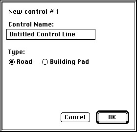
Choose New control line... from the Plan menu. A dialog box (see
Figure 5-1) will appear. Name the control
line and click OK. The name will appear in the Active menu.
Figure 5-1
You can now enter the horizontal alignment for that control line.
Choose New IP from the Plan menu. The cursor will change to a cross
when it is over the Plan window. Hold the mouse button down and drag
until the horizontal intersection point (IP) is in the desired
position. A small circle ( ) will be drawn
here to represent the IP. For each new horizontal IP, choose New IP
and position in the same manner. A line will be drawn to the previous
IP with a curve inserted for the previous IP.
) will be drawn
here to represent the IP. For each new horizontal IP, choose New IP
and position in the same manner. A line will be drawn to the previous
IP with a curve inserted for the previous IP.
Note: If the deflection angle at an IP is less
than 0° 15'00", HighRoad will not insert a curve. The radius
will be set to zero, indicating that no curve is to be used. If the
radius is set to zero and locked, no curve will be inserted no matter
what the deflection angle. This option may be useful if you wish to
use HighRoad to create drainage or sewerage longitudinal sections. If
you choose a curve radius larger than will fit between the adjacent
curves, a warning will be displayed, and the radius set to the
maximum that can fit without overlapping the next or previous curves.
These parameters are set in the dialog box as shown in
Figure 5-2. Double-click on the IP when the
cursor is a four pointed arrow ( ) to see the dialog box.
Continue until you have entered all the horizontal IPs for the
road. The control line can temporarily run off the edge of the model
while you are selecting the correct alignment. Once the horizontal
alignment is in place, you can view the profile along this alignment
and design the typical section and gradeline.
Note: You cannot display the profile, cross
sections or the full plan view if the control line runs off the edge.
You should not attempt to display any other view other than the plan
of the control line, if the control line runs off the edge of the
terrain model.
Editing the horizontal alignment
You can change the position of any of the horizontal IPs. Move the
pointer to the IP you want to adjust and it will change to a four
pointed arrow ( ). Drag the arrow to the
new location. HighRoad will redraw the new view of the plan. You can
also precisely specify the location of the IP and the details of the
curve data. Double-click on the IP when the cursor is a four pointed
arrow (
). Drag the arrow to the
new location. HighRoad will redraw the new view of the plan. You can
also precisely specify the location of the IP and the details of the
curve data. Double-click on the IP when the cursor is a four pointed
arrow ( ). The dialog box shown in
Figure 5-2 will appear on the screen.
). The dialog box shown in
Figure 5-2 will appear on the screen.
Figure 5-2
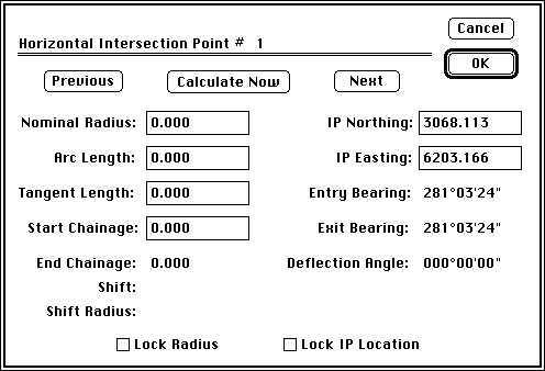
Change the position of the IP or the elements of the curve using
the usual editing techniques. Click Calculate Now to show the effect
of any change on the other curve data. If you make a change and then
move to another field, the curve data will be recalculated. Click
Previous and Next to view the previous or next intersection point
along the alignment.
Note: Do not drag any horizontal IP outside the
terrain model, or locate it so that the control line crosses outside
the terrain model. If the first or last IP is dragged off the edge of
the terrain model, HighRoad beeps as a warning and returns the IP to
its original position. IPs other than the first or last points can
correctly be off the model. You can drag the control line off the
edge of the terrain model while you are adjusting the horizontal
alignment. As the alignment of the control line is refined it should
be moved within the terrain. It is necessary for the control line to
be within the terrain model when you display a profile or cross
sections, or any other window which depends on calculation of natural
surface along the control line or along a cross section. If you try
to open one of these windows while the control line is not entirely
within the terrain model a warning will be displayed and the window
will be closed.
You can also insert and delete horizontal IPs. Insert IP... and
Delete IP... are available in the Plan menu when two or more IPs have
already been added. To insert an IP into an alignment which has
already been laid out, find the number of the IP (by double-clicking
on it) after which you wish to insert an extra IP. Choose Insert
IP... and a dialog box which asks for this number will appear. The
extra IP will be inserted half way between the IP you nominated and
the next IP. You can then drag it to its correct location, or
relocate it by double-clicking it and editing the values shown in the
dialog box.
To delete an IP, choose Delete IP... The cursor will change to an
X shape. Position the cursor over the IP to be deleted and click. The
IP will be deleted. Choose New IP to add an extra IP to the end of
the horizontal alignment.
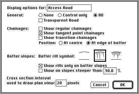
You can select what information HighRoad will display about the
control line in the Plan view. Select Show <Control line
name> details... from the Plan menu. A dialog box with the
name of the control line, as shown in Figure
5-3, will appear. You can choose to show no details, control line
only or the whole road.
Note: Details about the road will only be shown
in the Plan view when you have designed a typical section and
gradeline for the road.
The transparent road option and the batter rill symbols are only
available when All is selected. If All is selected and the control
line runs off the edge of the road only the control line will be
shown. Transition chainages will not be shown unless superelevation
or plan transitions have been calculated. (See Chapter 8,
Transitions, page 9-1.)
Figure
5-3
Redrawing the plan
Redrawing the plan view of the road after scrolling may take some
time. The speed of drawing is influenced by the size of the straight
segments which are drawn to represent curved lines. With long
segments, the speed of drawing is faster but the drawing appears as a
series of straights rather than as a smooth curve. You can change the
segment length by typing in the required distance between cross
sections in pixels. Selection of a larger distance between cross
sections (for example, 40 pixels) will speed up the redraw
considerably but may not be suitable for detailed work or when
printing.
You can also choose not to display any mark at all for points.
This means that you do not have to wait for the dots to be drawn for
points. This speeds up redraw noticeably on slower computers. In
combination with redraw interruption (as discussed below) this can
speed up your work considerably.
HighRoad allows you to choose whether plan redrawing will be
stopped when the mouse is clicked. Select Preferences... from the
Edit menu. Check the box labelled Stop plan redraw on mouse click.
This setting will be remembered by HighRoad. Once selected, plan
redraw is stopped when the mouse is clicked. This is useful if you
are zooming in on part of the plan. You may need to zoom in several
times to get to the scale that you want. Instead of waiting for the
plan to fully redraw each time, you can wait just long enough to see
sufficient detail to know where you are, then choose Zoom again. As
you click on the View menu the plan drawing will stop, allowing you
to select Zoom again. (This also applies if you are using the Command
( ) key on Macintosh or the Alt (
 ) key on Windows to zoom.) Be aware that the plan
view may be incomplete if the mouse button is down at any time during
plan redraw.
) key on Windows to zoom.) Be aware that the plan
view may be incomplete if the mouse button is down at any time during
plan redraw.
Plan drawing does not stop under all conditions. The first time
contours are drawn they also have to calculated. This cannot be
interrupted. Subsequent redraws are much faster (providing sufficient
memory was available to store the contours) and can be interrupted by
a mouse click. You can also force an update of the plan view. If you
interrupt the drawing of the plan view, you may be left with a partly
completed plan. To force the Plan window to be redrawn, click on the
size box in the lower right corner. The Plan window will be redrawn
completely.
Multiple
control lines

Note: This option is available only if you are
using HighRoad Plus, HighRoad Pro or have purchased the license to
use the Extra control lines module.
You can add up to 100 control lines in any project. Simply select
New control line... from the Plan menu. A dialog box (as shown in
Figure 5-1) which allows you to name the
control line, will appear. Each time you add another control line its
name will also appear in the Active menu. The current control line
(the one on which you are working) has a tick against it in the
Active menu and all views of the road (Plan, Profile, Cross Section
etc.) show information relating to that control line. The background
of the current control line is displayed in yellow. The details
displayed about each control line in the Plan view will depend on
what you have selected for that control line. Choose Show
<Control line name> details... from the Plan menu. A
dialog box with the name of the control line, as shown in
Figure 5-3, will appear.
Choose the details to be shown for that control line. Remember
that details about the control line will only be shown in the Plan
window when you have designed a typical section and gradeline for the
control line.
Note: At present no account is taken of
overlapping control lines when calculating quantities or batter
slopes unless all control lines which intersect the current one have
been constructed. See Constructing the road, page
4-18.
Locating a point on a
control line

You can easily calculate the location of a point along the current
control line given its chainage and offset and the bearing and
distance to a reference point. Choose Location on control
line... from the Plan menu and a dialog box as shown in
Figure 5-4 will be presented. Enter the
chainage and offset of the location required and the northing and
easting of the reference point if required.
Figure 5-4
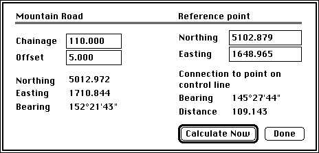
The northing, easting and the bearing at the control line and the
bearing and distance to the reference point will be displayed after
you click Calculate Now (or move to another field by tabbing or by
clicking in the other field).
If you type a chainage which falls outside the limits of the
design information for this control line, the chainage will be
adjusted to the nearest location actually within the design
information. Likewise, enter the chainage and offset of the location
required and its northing, easting and the bearing at the control
line will be displayed after you click Calculate Now or move to
another field by tabbing or by clicking in the other field.
| Previous |
Next |