|Creative Engineering
home page|
|Table of contents |
Learning HighRoad |
Using HighRoad|
Reference|
| Previous |
Next |
Chapter 2 HighRoad tutorial - Part 3
Designing an
intersection and side road

Note: This option is available only if you have
the Intersection module. This module is included in HighRoad Plus and
HighRoad Pro and is optional in other models.
In preparation for the next part of the tutorial you should create
another file to work with.
Note: If you have taken a break between tutorial
sections, you first need to Open the appropriate file.
* Open the file named Tutorial Part 2.rdd.
* Choose Save as... from the File menu.
* Name the file Tutorial Part 3.rdd.
You will now design an intersection and side road for the project.
This road will intersect with Frontage Road. An intersection is
always added to the active control line. Currently there is only one
road (Frontage Road) in the project. Therefore it is the active
control line. (The Active menu shows a tick against the active
control line.)
Adding an intersection
To locate the intersection you will click to the side of Frontage
Road where you wish to position the side road.
* Choose Place intersection on Frontage Road...
from the Plan menu.
The cursor will change to an intersection shape ( ).
).
* Click between points 8 and 23 to
indicate the side and location of the side road.
An intersection will be created on the left side of Frontage Road.
(Chainages on Frontage Road increase towards the top of the Plan
view.) All the geometry and vertical alignment calculations have been
completed automatically. The default settings for the intersection
are a radius of 7.5 metres for both left and right kerb returns, and
a deflection angle of 90 degrees. All other information is calculated
from the properties of Frontage Road, and the location of the
intersection on it. Your project plan should appear as in
Figure 2-12.
Figure 2-12
Adjusting the details of the intersection
* Move the cursor over the intersection.
The cursor will change to a hand shape.
* Drag the intersection along Frontage Road.
* Drag the second IP of the side road to change the angle
of the intersection.
The kerb returns are automatically adjusted to fit the new
location. The vertical alignment of the side road is also
automatically adjusted to match the new location.
* Drag the second IP of the side so it is once
again at right angles to Frontage Road.
* Drag the intersection to its original position.
* Adjust both the location of the intersection and the angle so
that the side road is positioned within the road boundaries.
The view on your screen should look similar to that shown in
Figure 2-13.
Figure
2-13
Control lines
* Click on the Active menu.
The three new control lines that have been created for this
intersection are shown in the Active menu, along with Frontage Road.
Side Road has a tick beside it -- this means it is the active control
line and all views (typical section, plan, profile etc.) will refer
to this control line. The new road is named Side Road, the kerb
returns named Left Return and Right Return. These are the default
names used by HighRoad. You can change the names of these control
lines.
* Choose Plan from the Window menu.
* Choose Show Side Road Details... from the Plan menu.
* Change the name to Internal Road.
* Choose Left Return from the Active menu.
* Choose Show Left Return Details... from the Plan menu.
* Change the name to Internal Rd L Return.
* Choose Right Return from the Active menu.
* Choose Show Right Return Details... from the Plan menu.
* Change the name to Internal Rd R Return.
Note: We recommend that you make a habit of
changing the default names used by HighRoad. In projects with more
than intersection you will have more than one road called Side Road
and so on.
* Move the cursor over the intersection.
The cursor will change to a hand shape.
* Double-click the intersection.
Figure
2-14
Intersection calculator
A dialog box as shown in Figure 2-14
will appear. The Intersection calculator is diagrammatic in that it
always shows the side road to the right and drawn at 90 degrees. The
left and right radii shown are always considered left and right in
relation to someone standing at the centre of the intersection and
looking along the side road.
Note: The data which appears in the Intersection
calculator may be slightly different to what is shown here due to a
slightly different location of the road in your project.
You can edit the details of the intersection.
* Select the left radius and change it to
10.000 m.
* Press Tab.
The appropriate tangent point chainages will be recalculated.
* Select the right radius and change it to
10.000 m.
* Click Calculate.
The appropriate tangent point chainages are updated again.
* Click OK to dismiss the dialog box.
Typical section
* Choose Internal Road from the Active menu.
* Choose Typical Section from the Window menu.
* Observe the shape of the typical section for Internal
Road.
Notice that the pavement width is 3.5 m on each side of the centre
line. The intersection was created on the left side of Frontage Road.
The typical section for Internal Road is modelled on the left half of
the typical section of Frontage Road. The left side of the typical
section for Internal Road is an exact match, the right side is a
mirror image.
* Select Frontage Road from the Active menu.
* Select Typical Section from the Window menu.
* Observe the shape of the typical section for Frontage
Road.
* Adjust the size of the Typical Section window so that it
occupies the top half of the screen and you can see the plan view of
the intersection below it.
The view on your screen should look similar to
Figure 2-15.
* Click on the left pavement.
* Change the width from 3.500 m to 6.000 m.
Notice that the plan is immediately redrawn to show the new road
width and the new intersection details.
Note: The Intersection calculator has a check box
called Keep widths synchronised with typical sections in the lower
left hand corner. This is active by default.
Figure
2-15
Profile
* Choose Internal Road from the Active menu.
* Choose Profile from the Window menu.
* Choose Fit to window from the View menu.
The profile should look similar to
Figure 2-16 .
The vertical alignment of Internal Road was automatically created to
match the elevation and crossfall of Frontage Road. The first and
second vertical IPs are set to remain synchronised with Frontage
Road. (This is the default setting and is indicated by the
double-circle around IP 1 and 2.) The 3rd IP is placed at ground
level at a chainage of 50 metres. The vertical alignment of Internal
Road will be automatically adjusted when changes are made to Frontage
Road or the location of the intersection.
Figure 2-16
* Double-click the first IP.
It is marked Synchronise with through road. The elevation of this
IP is approximately 38.125 m, and has a grade of 3%.
* Double-click the second IP.
It is marked Synchronise by grade with through road.
* Click OK.
* Choose Frontage Road from the Active menu.
* Choose Show IP Location from the Profile menu.
* Adjust the middle IP so that the elevation is 37.6
m.
* Choose Internal Road from the Active menu.
* Choose Fit to window from the View menu.
You can see that the elevation of both the first and second IPs on
Internal Road have been lowered to match the change made to Frontage
Road. The location of the third IP remains unchanged.
* Choose Plan from the Window menu.
If you look closely you will see that the batter lines are
different. They are now further out from the intersection.
Figure 2-17
* Choose Frontage Road from the Active menu.
* Choose Typical Section from the Window menu.
* Click on the left pavement link crossfall and change it
to +3.0%.
* Click OK.
* Choose Profile from the Window menu.
* Choose Internal Road from the Active menu.
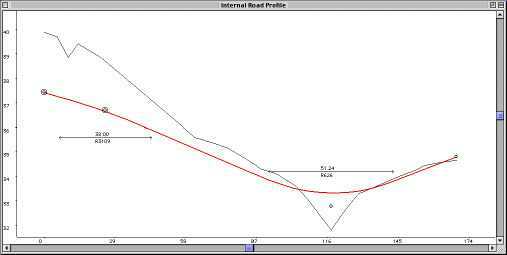
As a result of changing the typical section of Frontage Road, the
profile of Internal Road has changed significantly. It should look
similar to Figure 2-17. The grade of
Internal Road has changed to +3.0% to match the crossfall of Frontage
Road. The third IP remains unchanged. It will remain wherever you
position it.
Vertical grading of kerb returns
The kerb returns are located in the plan view, and remain
synchronised as changes are made to the through road, the
intersection is moved, or the side road is dragged. The same kind of
synchronisation is also maintained with the grading of the kerb
returns.
* Choose Internal Rd L Return from the Active
menu.
The profile should look similar to that shown in
Figure 2-18.
Figure
2-18
The start of this control line matches with the edge of pavement
of Frontage Road at the kerb return tangent point. The right end
matches the edge of pavement of Internal Road at the kerb return
tangent point.
Follow the steps outlined below to see how the kerb return grading
is automatically updated to match changes in its attached roads.
Figure
2-19
* Choose Frontage Road from the Active menu.
* Choose Typical Section from the Window menu.
* Click on the left pavement link and change it to
-3.0%.
* Choose Internal Rd L Return from the Active menu.
* Choose Profile from the Window menu.
The profile should now be similar to Figure
2-19. The end (right) of the profile for the left kerb return is
now on a downward grade and is lower than in
Figure 2-18. It matches the latest grading
of Internal Road which is now downwards from Frontage Road, matching
the crossfall of Frontage Road. The start (left) of the grade line is
now lower, to match the pavement of Frontage Road which is lower
because the crossfall was changed to -3%.
As with other control lines you can display cross sections along
the kerb return to examine in detail the shape of the intersection.
* Drag the size box of the Profile window and
reposition it so it occupies the top left quarter of the screen as
shown in Figure 2-20.
Figure 2-20
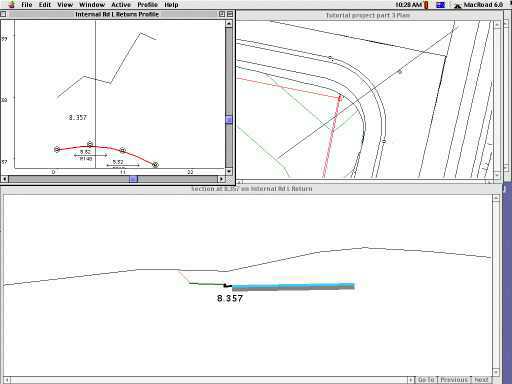
* Choose Plan from the Window menu.
* Drag the size box of the Plan window and reposition it so it
occupies the top right quarter of the screen. (See
Figure 2-20.)
* Click on the Profile window to activate it.
* Slow drag across the Profile window from left to right.
As you drag, the vertical line indicates chainage. The location of
this cross section shows in the Plan window as you drag. With the
line central in the profile, release the mouse button. The cross
section at that chainage is displayed.
* Adjust the size of the Cross Section window to the
top half of screen.
* Move the Cross Section window to the bottom half of screen.
Your screen should look similar to Figure
2-20. This is a useful layout for design. You can drag in the
profile window to see any cross section, and as you drag, the
location of the section line is shown in the plan.
Extending Internal Road
Internal Road can be extended by adding more IPs in the Plan
window.
* Click on the Plan window.
* Click on the zoom box (upper right) to expand it to the full
screen size.
* Choose Fit to window from the View menu to position the
plan view.
* Choose Internal Road from the Active menu.
* Choose New IP from the Plan menu to add another IP.
* Click in the middle of the cul-de-sac area between points
14 and 17.
Your screen should look similar to Figure
2-21.
Figure 2-21
* Adjust the position of the second IP so that
the road fits within its reserve.
* Double-click the second IP and adjust the radius to
100 m to better fit the reserve.
Adjusting the grading of Internal Road
You can adjust the grading to suit the design requirements.
* Choose Profile from the Window menu.
* Click the zoom box to expand it to the full screen size.
* Choose Fit to window from the View menu.
* Move the pointer over the over the third IP.
When it is close enough to drag the IP, the pointer will change to
a four point arrow ( ).
).
* Press the mouse button and drag the third IP to the
position shown in Figure 2-22.
* Choose New IP from the Profile menu.
Figure 2-22
* Place the fourth IP as shown.
* Choose Save from the File menu.
Effect of intersection on earthworks quantities
If you calculate the earthworks volumes for Frontage Road now that
an intersection has been added, you will see that the volumes will be
reduced. If you display Frontage Road you will see why.
* Choose Plan from the Window menu.
* Choose Internal Road from the Active menu.
* Choose Show Internal Road details... from the Plan menu.
* Select None from the dialog box that appears.
* Click OK.
Follow these steps again to make the same change to the display of
both kerb returns.
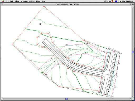
The Plan view on your screen should look similar to
Figure 2-23. Only Frontage Road is visible
and you can see a gap at the intersection location. This gap is
defined by the tangent point chainages of the left and right kerb
return on Frontage Road. When HighRoad calculates the quantities for
Frontage Road the volume in the gap is ignored.
Figure
2-23
Similarly when HighRoad calculates the quantities for Internal
Road, the calculations will start from the tangent point chainages of
the left and right kerb return on Internal Road. The intersection
volumes are made up of the volumes for the left and right kerb
return. Calculate the quantities for the right kerb return.
* Choose Internal Rd R Return from the Active
menu.
* Choose Text from the Window menu.
Note: The list of points to create
this terrain model may appear.
* Click the close box.
* Choose Text from the Window menu.
A blank Text window will appear.
* Choose List quantities... from the Text menu.
* Click all the boxes.
* Click OK.
A list of chainages and cut and fill end areas of cross sections
of the right side of the intersection will be shown in the Text
window. Follow these steps again to calculate the quantities for
Internal Road L Return.
Continue on to the next part of the tutorial or take a break.
| Previous |
Next |