Chapter 2 HighRoad tutorial - Part 4
![]()
Note: This option is available only if you have the Intersection module. This module is included in HighRoad Plus and HighRoad Pro and is optional in other models.
In preparation for the next part of the tutorial you should create another file to work with.
Note: If you have taken a break between tutorial sections, you first need to Open the appropriate file.
* Open the file named Tutorial Part 3.rdd.
* Choose Save as... from the File menu.
* Name the file Tutorial Part 4.rdd.
A cul-de-sac is always added to the end of an existing road. In this project, the cul-de-sac will be added to the end of Internal Road. Before you add the cul-de-sac, check that Internal Road is the active control line. The Active menu shows a tick against the active control line. In this case there are four control lines, and Internal Road should be the Active one.
* Choose Place Cul-de-sac on Internal Road... from the Plan menu.
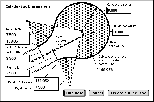
A Cul-de-sac calculator as shown in Figure 2-24 will be displayed. The geometry of the cul-de-sac has been calculated using the following the default dimensions:
cul-de-sac radius 8.0 m
left and right radius 7.5 m
offset from the road control line 0

The left and right width are initially set at the width of the first link of the typical section on the left and right of the road. If you have a kerb on the edge of this link, the control line of the cul-de-sac will follow along the inner reference line of the kerb. This allows the cul-de-sac kerb to be graded to suit the drainage design of the cul-de-sac, rather than the grade of the road control line.
You can change any of these dimensions and the dependent chainages and dimensions will be calculated to suit.
* Change the head radius to 9.000 m.
* Click Calculate.
Notice that the tangent point chainages have changed.
* Click Create cul-de-sac.
* Choose Cul-de-sac from the Active menu.
* Choose Show cul-de-sac details... from the Plan Menu.
A dialog box which allows you to choose how the cul-de-sac will be displayed in the Plan.
* Check the box Show regular chainages .
* Click OK.
* Choose Cross Section from the Window menu.
* Choose Cross Section layout from the Cross Section menu.
* Set the cross section interval to 5.000 m.
* Choose Plan from the Window menu.
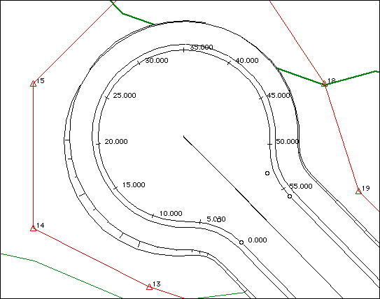
You will see that HighRoad has created a cul-de-sac on Internal Road complete with all the geometry and vertical alignment information. Chainages will be shown at the cross section interval currently specified. Your project plan should look similar to Figure 2-25.

The cul-de-sac is similar to an intersection in terms of the techniques that are used. An additional control line is created for the grading around the head of the cul-de-sac. You can see by looking at the chainages on the control line that it starts at the left tangent point, goes around the head of the cul-de-sac and ends at the right tangent point.
Cul-de-sac grading
The gradeline for the cul-de-sac can be adjusted to optimise the design. You can view the cul-de-sac profile and cross sections, and adjust them where necessary.
* Choose Cul-de-sac from the Active menu.
* Choose Profile from the Window menu.
The grading of the cul-de-sac on your screen should be similar to Figure 2-26. The grading for your project may be slightly different because of small differences in the horizontal location and vertical grading of Internal Road. The grading follows around the edge of the pavement, along the lip of the kerb and gutter. This grading is critical for drainage, from the point view of having sufficient grade in the gutter, and pavement slopes that the grading produces.

The double circles at each IP mean that the IPs are synchronised with the road they belong to. If you change the grading of the road, the cul-de-sac grading will be adjusted to match. The start and end IP are synchronised in chainage and elevation to match the pavement of the road at the tangent points. The second and fourth IPs are synchronised in elevation so that the grade to the nearest end matches the grade of the road at the tangent points. The chainage of these IPs will not be changed when the cul-de-sac or road design is changed. You have to manually adjust the chainage if necessary.
The middle IP is synchronised in chainage and elevation to match a section through the head of the cul-de-sac, so that the crossfall from the centre of cul-de-sac to the mid-point of the grading will be correct.
To inspect the adequacy of the cul-de-sac grading it is useful to display critical cross sections of the cul-de-sac. To facilitate this arrange the Plan, Profile and cross section windows so that all are visible and are sized appropriately for the task at hand.
* Drag the size box of the Profile window to reduce it to the top third of the screen.
* Choose Plan from the Window menu to make the Plan window active.
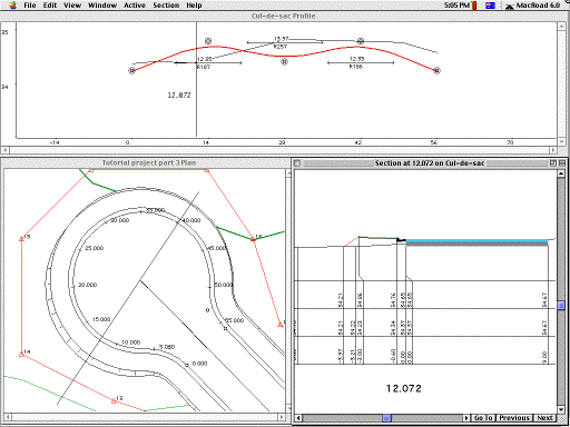
* Resize the Plan window and position it so it occupies the bottom left two-thirds of the screen as shown in Figure 2-27.
* Click on the Profile window to activate it.
* Slow drag across the Profile window from left to right.
As you drag, the vertical line indicates chainage. The location of this cross section shows in the Plan window as you drag.
* Release the mouse button to display a cross section around chainage 12.
* Resize the Cross Section window to the size shown in Figure 2-27.
* Drag the Cross Section window to the position shown.
Figure 2-27 shows the cross section line being dragged in the Profile window, the cross section line being displayed in the Plan view, and the resulting cross section. This particular cross section shows that the pavement is almost horizontal, which is not suitable for the cul-de-sac drainage. If you examine a number of cross sections, it will be apparent that cross sections in the vicinity of the second and fourth IP are too flat. To fix this, the gradeline needs to be lowered in these areas. These IPs cannot be lowered without effecting the grade from the start and to the end. (Remember that the start and end IP are synchronised in chainage and elevation to match the pavement of the road at the tangent points. The second and fourth IPs are synchronised in elevation so that the grade to the nearest end matches the grade of the road at the tangent points.) A solution to this is to move the second IP closer to the start, so that the grade is maintained, but the elevation of the grade line in this area is lowered. Similarly for the fourth IP. To adjust the second IP you first have to deactivate its synchronisation to the first IP.

* Double-click the second IP.
An IP dialog box will appear.
* Uncheck the box marked Synchronise grade to start of cul-de-sac.
* Note the grade from first IP.
It should be approximately 3.9%. Your project may be slightly different.
* Click OK.
* Drag the second IP to about chainage 5 m.
* Double click the second IP.
* Set the grade to 3.9% and click in another field and the elevation will be recalculated.
* Check the box marked Synchronise grade with start of cul-de-sac.
* Click OK to close the IP dialog box.
To adjust the fourth IP you first have to deactivate its synchronisation to the last IP.
* Double-click the fourth IP.
A dialog box will appear.
* Uncheck the box marked Synchronise grade to end of cul-de-sac.
* Note the grade from last IP.
It should be approximately 3.9%. Your project may be slightly different.
* Click OK.
* Drag the fourth IP to a chainage about 5.000 m from the last IP.
* Double click the fourth IP.
* Set the grade to 3.9% and click in another field and the elevation will be recalculated.
* Check the box marked Synchronise grade with end of cul-de-sac.
* Click OK to close the IP dialog box.

You should have a profile similar to that shown in Figure 2-28. Check that the crossfall is now satisfactory by displaying a some cross sections from chainage 7 to 15.
* Drag in the Profile window and release the mouse button to display a cross section around chainage 7.
* Click the Next button in the Cross Section window which will show cross sections at 5 metre intervals.
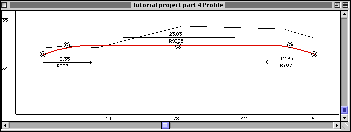
All the sections now have good crossfall. However the changes have created a problem with the grade around the head of the cul-de-sac as seen in Figure 2-28.
For ease of drainage, it may be best to raise the middle IP so that the cul-de-sac grades in the same direction as the road. You can check the feasibility of this by examining the cross section at that chainage.
* Drag in the Profile window and release the mouse button to display a cross section around chainage 28 m.
Your screen should show a crossfall of 0.26 m from centre of the cul-de-sac to lip of gutter. As a trial, adjust the elevation of the middle IP up by 0.13m . The middle IP is synchronised in chainage and elevation to match a section through the head of the cul-de-sac.
* Double-click the middle IP.
An IP dialog box will appear.
* Uncheck the box marked Synchronise with head of cul-de-sac.
This will de-activate the synchronisation.
* Increase the elevation by 0.13 m.
The grade should be around 0.45%.
* Click OK.
Your profile should now be similar toFigure 2-29.

Test that the crossfall is now adequate for cross sections around the cul-de-sac.
* Click Previous or Next in the Cross Section window.
* Check the cross sections and observe that sufficient crossfall exists.
This design can should be further optimised but is sufficient for the purpose of demonstrating the features of cul-de-sac design in HighRoad. If you make any changes to this cul-de-sac road, such as change its grading, only the ends of the cul-de-sac grading will remain synchronised. The middle IP will require manual adjustment after any change.
* Choose Save from the File menu.
Continue on to the next part of the tutorial or take a break.