This chapter shows you how to create perspective views of your designs. You can create a simulation of driving along the road and flying around the site, and specific views of the terrain.
Note: The options referred to in this chapter are not yet available for Windows. Otherwise they are available if you have the 3D module.
![]()
To create a drive through simulation you need to have completed a horizontal alignment, a typical section, and a profile of the road. The drive through simulation is saved as a colour QuickTime movie, so you also need QuickTime installed in the System folder.
Note: If you have a screen saver installed, you may find that it will effect the construction of the scenes. You may have to turn it off while the scenes are being constructed.
To make a QuickTime movie, first check that QuickTime is in the System folder and any screensaver installed is turned off. Set your monitor to 256 colours and make sure you have plenty of free space on your hard disk. (As a guide, a drive through simulation for two kilometres of road can require 6Mb of disk space). Choose Drive through simulation from the Window menu. When the Drive through simulation window is in front choose Drive through simulation... from the 3D View menu. A dialog box as shown in Figure 15-1 will appear. Choose the desired settings. You may wish to experiment with the settings in order to get the best simulation for the design. (The information on pages 15-3 and 15-4 should give you some guidance in setting the various parameters offered.) Click OK, then name the movie file and click Save.
HighRoad will create the movie. The simulation is created by constructing a series of perspective views of the road as it would be seen from a drivers position. As each view is created it is stored on the hard disk as part of a QuickTime movie file. The number of views that can be created is limited by the amount disk space available. Creation of the drive through simulation can be quite time consuming. You cannot cancel this process. If you change the size of the 3D window before creating the movie in HighRoad, the size of the file will be proportionally smaller or larger.
A QuickTime movie can be replayed with the MoviePlayer application that comes with QuickTime. To view the simulation, quit HighRoad and double-click the drive through movie that you created. MoviePlayer will open the movie. The views are played back quickly (like a movie film) to create the illusion of driving along the road. The illusion will be most effective if the scenes are close together, and they can be played back very quickly. The MoviePlayer allows you to view individual scenes, cut and paste frames into other applications, print frames, and so on. A QuickTime movie can be viewed by other applications.
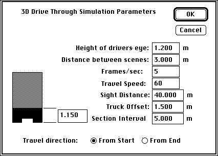
You can play the drive through in the reverse direction (i.e. from the end). The number of frames/sec can be set to properly simulate travel at a specified speed. The values of travel speed, distance between scenes and frame rate are interdependent and a change in any one of these will cause the others to be recalculated when you move to another field by tabbing or using the mouse.
This is the height of the drivers eye above the control line of the pavement. The drivers eye is positioned 1.2 m to the left of the road control line. (This is fixed and cannot be changed by the user.) The direction of viewing is towards a point 20 metres in front of the driver and the same distance from the centre line. The elevation of this point is halfway between the pavement surface and a point level with the drivers eye.
Distance between scenes
File size is affected by this setting. Creation of the movie will be faster if you choose a larger distance between scenes but this will also reduce the quality of the 3D view.
The appropriate distance to select depends on a number of factors. Your computer and its available memory, the length of road to be viewed, the purpose of the simulation and the replay speed (frames/second) may influence the choice of distance between scenes. Trial and error may be the best way for you to determine the appropriate distance for your particular job.
Section interval
This is the distance between the cross sections which are used to draw each scene. File size is affected by this setting. The scenes look more realistic the closer the spacing between sections. However the closer the spacing between sections, the longer it will take to calculate each scene.
Truck offset
This is initially set at 1.5 m to the left of the centre line (-1.5 m). If the left lane is 3 m wide then the truck is driving in the middle of the left lane. This offset can be changed for different road widths. The above example would be changed to 1.5 m to the right of the centre line (+1.5 m) where vehicles travel on the right hand side of the road.
The 3D drive through simulation allows you to visualise sight distance. The simulation can be used to test whether a nominated stopping sight distance is available. Stopping sight distance is available if the driver can see an object on the road at the nominated distance. A truck is shown in the simulation and the dimensions of the rear of the truck are adjustable to allow sight distance to objects of various heights to be examined. The distance from the driver's eye to the rear of the truck is set to the sight distance.
The following example illustrates the method used for checking sight distance. Assume the design is to provide a stopping sight distance of 50 m to an object with a height of 1.05 m. Choose Drive through simulation... from the 3D View menu. Set the sight distance to 50 m and the height of the black part of the truck to 1.05 m.
If the black part of the back of the truck disappears completely from view around a curve or over a crest during the simulation, then the required sight distance cannot be provided. Note the location of view position when the truck disappears from sight (the title of the window shows the view position) so that you can adjust the longitudinal profile or the typical section in that location. You can pause the playback by pressing the mouse button.
Note: This should be used as a guide only. The resolution of the screen limits the accuracy to which the road and the vehicle can be depicted. Other methods should be used to verify any conclusions drawn from this simulation.
![]()
You can create a perspective view of the terrain in the 3D View window. HighRoad does this by taking a snapshot of the site. You can alter the position of the camera and the point on the project that the camera is aimed at. If you want the perspective view to show a road then you need to construct the road first. (See Constructing a road or pad, for details.) Choose Save As... and save your file under a new name before constructing the road. Choose Construct <Control line name> from the Plan menu.
Choose Show camera from the Plan menu to position the camera and its direction of view in the Plan window. A blue line attached to a blue filled circle will appear on the screen. The blue filled circle represents the camera position. The blue line shows the direction to the point on the project that the camera is directed at.
Note: You may have to shrink the Plan view to locate the camera. Choose Shrink from the Edit menu.
Position the cursor over the blue filled circle. The cursor will
change to a four pointed arrow (![]() ). Drag the arrow to the desired location of the
camera. Double click on the blue filled circle to precisely set the
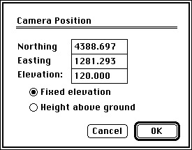
position and elevation of the camera. A dialog box as shown in
Figure 15-2 will appear. Set the camera
position precisely by specifying its Northing and Easting. The
elevation of the camera can be fixed or at a nominated height above
the ground. You can also set the location and elevation of the camera
target position. Place the cursor at the opposite end of the blue
line. The cursor will change to a four pointed arrow. Drag the arrow
to the desired camera target position. Double click on the four
pointed arrow to set the precise location and elevation of the target
position.
). Drag the arrow to the desired location of the
camera. Double click on the blue filled circle to precisely set the
position and elevation of the camera. A dialog box as shown in
Figure 15-2 will appear. Set the camera
position precisely by specifying its Northing and Easting. The
elevation of the camera can be fixed or at a nominated height above
the ground. You can also set the location and elevation of the camera
target position. Place the cursor at the opposite end of the blue
line. The cursor will change to a four pointed arrow. Drag the arrow
to the desired camera target position. Double click on the four
pointed arrow to set the precise location and elevation of the target
position.
A good position for the camera is at a fixed elevation above the highest point of the terrain and well outside the terrain model (at a distance of about twice the size of the project). Set the target end at ground level. Once you have positioned the camera, select 3D View from the Window menu. HighRoad will produce a 3D view of the terrain.
You can then save this view as a PICT file (select Export 3D View as PICT file... from the File menu) or as a fly-around movie (select Save as Quicktime movie... from the File menu). You need Quicktime in the System folder to save as a fly-around movie. See page 15-1 for more details about Quicktime movies.
You may need to experiment with a variety of camera and target positions to get the best view. It is helpful to have both the 3D View window and the Plan window visible.