|Creative Engineering home page|

|Table of contents | Learning HighRoad | Using HighRoad| Reference|

| Previous | Next |

Chapter 2 HighRoad tutorial - Part 1


This chapter shows you how to use HighRoad to design a simple project. You will create a terrain model, and then layout a horizontal alignment, design a typical section, design a gradeline, view the cross sections and calculate earthworks quantities for a road. You will also design an intersection and side road with a cul-de-sac, a building pad and a dam. These exercises will teach you many of the basic features of HighRoad.

This tutorial is divided into parts to make it easy to follow. It also allows you to complete one section at a time and to come back later and use just one of the parts to review a particular issue. The parts that make up the tutorial are:

* Creating a terrain model

* Designing a road

* Designing an intersection and side road

* Designing a cul-de-sac

* Designing a building pad and dam.


To use this tutorial you will need HighRoad version 6.0 and two files. These are:

* Tutorial points list.txt

* Tutorial feature library.rdl

These files are found in the HighRoad tutorial folder that is part of the HighRoad package.


Creating a terrain model

For Macintosh:

* Double-click on the HighRoad icon.

For Windows:

* Choose HighRoad from the Start menu under Programs/Creative Engineering.


Note: The first time you start HighRoad for Windows after the installation you will be asked to enter a serial number and authentication key. Your serial number and authentication is printed on the CD label. HighRoad for Windows is set up with alternative shortcuts:

HighRoad

HighRoad (full screen)

Choose whichever is best for your work.


A copyright notice will appear on the screen.


Note: If you are not licensed to use HighRoad you must not proceed.

* Click New.

A dialog box will appear on the screen so that you can choose the source of the survey data.

* Select Text file.

* Click OK.

A file selection dialog box will appear on the screen.

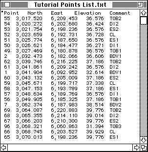
* Open Tutorial points list.txt

The text file will appear on the screen as shown in Figure 2-1. It shows for each point, in order from left to right -- point number, northing, easting, elevation and comment.

Note: This example is in metric units (metres) and so you should choose Metric and Degrees from the Preferences dialog box. (Choose Preferences from the Edit menu.)


Figure 2-1

Each of the points in this example has a comment. These comments can be used to form feature strings automatically. The comments are alphabetical characters optionally followed by a number. The alphabetical portion of the comment is its feature code. Where there is more than one feature of a particular type, a number is added to distinguish between features of the same type. Codes used in this example are:

Code

Meaning

BDY

Property boundary

DI

Ditch invert

TOB

Top of bank

CL

centre line

ES

Edge of shoulder

GULLY

Natural gully

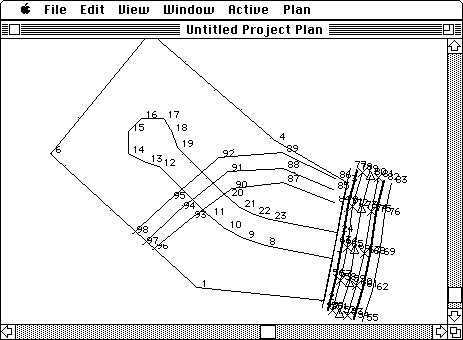
There is only one centre line on this job, so it is denoted CL. There are two shoulder edges, so these are denoted ES1 and ES2. To form a feature HighRoad first finds all points with the same comment (for example ES1). These points are then sorted in point number order and joined in that order. For example, point 51 is the first point of the Edge of Shoulder feature #1 (ES1). It would be joined to point 58 which is the second point in this feature.


HighRoad keeps a library of feature definitions so that you only have to define each feature once -- this definition can then be used on future jobs. The feature library provided includes a definition for a centre line feature (CL) and for a natural gully (GULLY) feature. You can look at or change these definitions in the feature library.

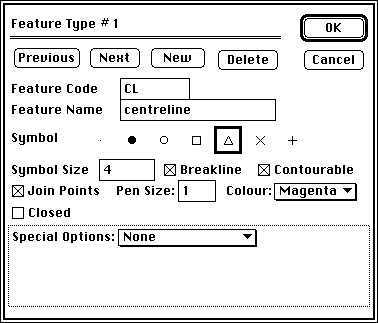
* Choose Feature library... from the Edit menu.

A dialog box as shown in Figure 2-2 will appear.


Figure 2-2


Note: If you have not used HighRoad before, HighRoad may not know the location of the feature library. If so, when you choose Feature Library from the Edit menu, a standard file dialog box will appear. It will ask you to locate the feature library. When you have found and selected the library, click the Library button in the dialog box. HighRoad will remember this location and will not ask you again unless you rename the library or move it to a different folder.

You can use the next and previous buttons to move between features.

* Click Next.

* Click Previous.

* Click Cancel.

* Choose Convert text file... from the Edit menu.


A dialog box will appear so that you can tell HighRoad the format of your text file.


* Select Point# Northing Easting Elevation [comment].


* Click OK.


HighRoad will read the text file and convert it into a HighRoad file. During the conversion HighRoad will scan the points for comments. It will find a match for points with the comments CL and GULLY already in the feature library, so it will join together these points to form a feature string. The comment TOB used in this example is not included in the feature library. When HighRoad finds a comment which is not in the feature library, a dialog box will appear asking if you wish to add this comment to the library.

Note: If someone has already completed this tutorial or used HighRoad, then the contents of the feature library may have changed. To ensure that the expected feature library is used, move the current feature library to another folder, and replace it with a copy of the original.


* Click Add to Library.

A dialog box similar to Figure 2-2 will appear. In this dialog box you can define how the feature TOB will appear. In this example TOB represents a feature called Top of bank. This feature should be specified as follows:

* Type in feature name: Top of bank

* Check Breakline

* Check Contourable

* Check Join Points

* Set Pen size to 1

* Set colour to Red

* Set symbol to dot (.)

* Set Symbol size to 0

* Special options should remain set to None

* Click OK.


Continue to add new features to the library when the appropriate dialog box appears. For each code, enter the details in the feature dialog box as follows:

Code Name Symbol Size Contour Break Join Pen Colour Closed Fill

BDY Boundary . 0 / / 1 Red / None

DI Ditch invert . 0 / / / 2 Cyan

ES Edge of shoulder x 4 / / / 1 Blue


The Plan window will appear as shown in Figure 2-3. It will display the points of the survey data and the features (as entered in the feature library). Each point will be displayed as a dot with a point number, or with the appropriate symbol if it is on a feature. You can show other information about each point.


Figure 2-3


* Choose Show point info... from the Plan menu.

A dialog box will appear. Experiment with various methods of displaying data about the survey points. When you are ready to proceed make sure that each point is displayed with its point number.

* Click OK.

The next tasks are to generate a triangulation of the model and to contour it. The first step is to mark the outside edge so that HighRoad can construct the triangulation correctly. To make it easier to identify points on the outside edge of the model, remove the display of the features from the screen.

* Select Hide features from the Plan menu.

* Choose Fit to window from the View menu.

* Scroll so that the lowest edge of the survey is in view.

Your screen should look similar to Figure 2-4.


Figure 2-4


Note: Depending on the size of your screen, the view on your screen may be different to those shown here.

To mark the perimeter you may need to enlarge, shrink or scroll the current view.

Note: You can change the scale in a number of different ways as follows:

* Choose Set scale... from the View menu.

Type in the required scale into the dialog box that appears. The scale must be in the range 1:50 to 1:200000.

* Choose a preset scale from the View menu.

You can change the scales which appear in the View menu by choosing Screen Scales from the Edit menu. The scales you select must be in the range 1:50 to 1:200000. These scales will then be displayed in the View menu.

* Choose Zoom from the View menu.

The cursor will change to a magnifying glass which contains a plus (). Click the point of interest and the view will be magnified by a factor of 2. The point of interest will be in the centre of the window. As a short-cut, you can select Zoom using the Command () key on Macintosh or the Alt () key on Windows.

* Choose Shrink from the View menu.

The cursor will change to a magnifying glass which contains a minus (). Click the point of interest and the view will be shrunk by a factor of 2. The point of interest will be in the centre of the window. As a short-cut, you can select Shrink by simultaneously using the Command () and Shift () keys on Macintosh or the Alt () and Shift () keys on Windows.

* Choose Pan from the View menu.

The cursor will change to a hand (). Drag the view in the direction you want to move it. The view will be redrawn in the new position when you release the mouse button. As a short-cut, you can select Pan by using the Option () key on Macintosh or the right mouse button on Windows.


Defining the perimeter

To create a terrain model of the survey data, first join the outside edge of the survey points in a clockwise order.

* Choose Join edge points... from the Plan menu.

A dialog box will appear. You can choose to join the points manually or automatically. We will join the points manually.

* Click the Manual button. Click OK.

The cursor will be shown as a cross when it is over the Plan window.

* Click on point 1 and then click on point 96.

A line will be drawn between the two points. Continue in a clockwise manner to click on points in the outside edge until you have clicked on the points 97, 98, 6, 5 and 4. After you have clicked on point 4, you may need to change the scale to ensure that you don't miss a point, particularly if you are using a small screen.

* Choose Zoom from the View menu and click on or near point 77.

The cursor will change to a magnifying glass () until you click on point 77. Continue to click on the following points in order 77, 78, 79, 80, 81, 82, 83, 76, 69, 62, 55, 54, 53, 52, 51, 50 and 49. You may need to scroll the screen and change the scale as you join the points. You may find the short-cuts for Zoom, Shrink and Pan useful here.

Note: If you make a mistake and click on the wrong point you can correct it.

* Choose Undo from the Edit menu.


* Click on point 1 (the first point) again to indicate that you have completed the outside edge.

The outside edge must enclose all points which are to form the terrain model. Any points outside this line will be made non-contourable and will not be included in the triangulation.


Contouring

HighRoad can now create a terrain model of the survey data.

* Choose Contours... from the Plan menu. (This item is near the bottom of the Plan menu. Do not confuse it with Show...Contours which is near the top.)

A dialog box will appear so that you can choose the format of the contouring.

* Set the minor contour interval at 0.25 m, major contours every 1 m and the tension at 10. Click OK.


HighRoad will complete a triangulation of the data and then draw the contours on the screen. Notice that the triangles are constructed to correctly model those features which are specified as breaklines. You can choose to show the terrain model in a variety of ways. Experiment with drawing the contours at different intervals and different tensions (choose Contours... from the Plan menu) and hiding and showing the contours and triangles (choose Hide/Show contours, Hide/Show triangulation from the Plan menu).

You have completed the first part of this tutorial. Save your work as Tutorial Part 1. You can continue on with the tutorial or take a break and come back to the tutorial later.

* Choose Save as... from the File menu.

* Name the file Tutorial Part 1.rdd.


| Previous | Next |