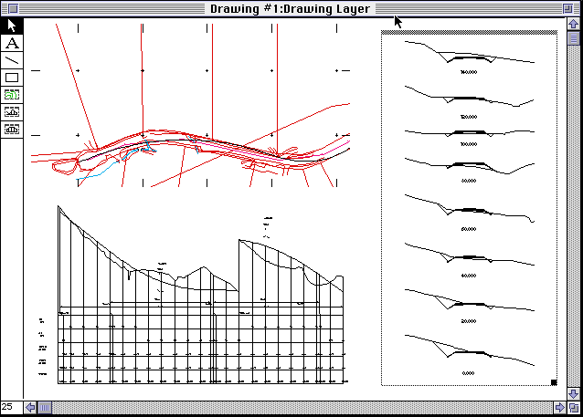
Figure
17-1
In the drawing layer there are seven drawing tools available as
follows:
 The arrow tool is used to select
existing objects on the drawing. This tool is shown selected and this
is the default tool when the window first appears.
The arrow tool is used to select
existing objects on the drawing. This tool is shown selected and this
is the default tool when the window first appears.
 The text tool is used to add blocks
of text to the drawing.
The text tool is used to add blocks
of text to the drawing.
 The line tool is used to add lines
to the drawing.
The line tool is used to add lines
to the drawing.
 The rectangle tool is used to add
rectangles to the drawing.
The rectangle tool is used to add
rectangles to the drawing.
 The Plan frame tool is used to add a
rectangular frame which displays part or all of the plan view of a
project.
The Plan frame tool is used to add a
rectangular frame which displays part or all of the plan view of a
project.
 The Profile frame tool is used to
add a rectangular frame which displays part or all of a profile of
the active control line.
The Profile frame tool is used to
add a rectangular frame which displays part or all of a profile of
the active control line.
 The Cross Section frame tool is used
to a rectangular frame which displays some or all of the cross
sections for the active control line.
The Cross Section frame tool is used
to a rectangular frame which displays some or all of the cross
sections for the active control line.
The frame tools are only available in the drawing layer. Further
details about each tool are discussed below.
The current reduction or enlargement of the drawing is shown as
percent at the bottom left of the drawing window.
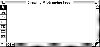
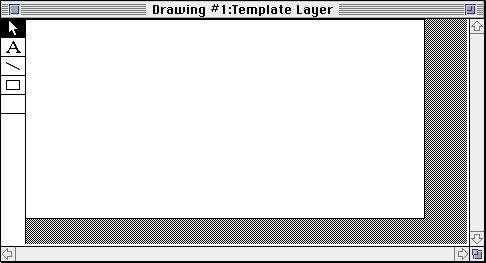
Drawing layers

Each drawing has a template layer and a drawing layer. The title
bar of the Drawing window shows the name of the drawing and the
current layer. Switch between layers by choosing Switch Layers from
the Drawing menu (a menu which appears when the Drawing window is in
front).
The template layer is analogous to a printed drawing sheet which
would include border and company title block complete with items
which are common to all drawings in the set. The drawing layer is
analogous to the drawing information which is added to the printed
sheet. This layer is where you will do most of your work.
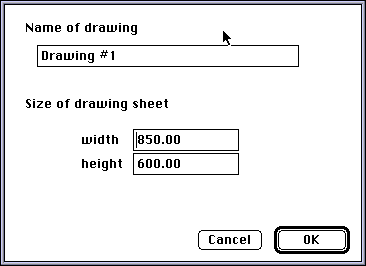
The template layer also contains information about the size of the
drawing. To see this information choose Get Drawing Info... from the
Edit menu when nothing is selected. (If an object is currently
selected the menu item will be titled Get Object info... Choosing it
will display information about the currently selected object.) A
dialog box as shown in Figure 17-2 will
appear. You can specify the size and the name of the drawing. The
name will be displayed as the title of the Drawing window title and
will be listed in the Drawing menu. The dimensions are currently in
millimetres with 2 decimal places.
Figure
17-3
Selection
tool

 The arrow or selection tool is used
to select any object in the drawing window. Only objects on the
current layer can be selected. On the drawing layer, objects on the
drawing layer can be selected, in the template layer, objects on the
template layer can be selected.
The arrow or selection tool is used
to select any object in the drawing window. Only objects on the
current layer can be selected. On the drawing layer, objects on the
drawing layer can be selected, in the template layer, objects on the
template layer can be selected.
When an object is selected then it can be acted upon by various
menu commands. Details about the selected object such as position can
be edited by choosing Get Object Info... from the Edit menu. The
information available varies depending on the type of object
selected.
Dimensions displayed in the Get Object Info... dialog box are
measured from the bottom left corner of the drawing. The selected
object can be deleted by pressing the delete key, or by choosing
Clear from the Edit menu. You can move the selected object one pixel
at a time by using the arrow keys.
Text tool

 The text tool is used to place a
block of text on the drawing.
The text tool is used to place a
block of text on the drawing.
Text is added by drawing a rectangle from top left to bottom right
when the text tool is active. (Click on the text tool to make it
active.) A rectangle will appear with the words Sample text in the
upper left corner. Choose Get Object Info... from the Edit menu. A
box will appear on the screen for where you can type in the text you
want to enter. You can enter up to 255 characters in a block of text.
You can drag the text rectangle and also adjust its shape by
dragging the bottom right corner. To edit the text, select the
appropriate text object. Choose Get Object Info... from the Edit
menu. Edit the text in the usual manner. When a text block is
selected you can also change the size of the text. Choose Text Size
in the Drawing menu. Select the appropriate size.
Line tool

 The line tool is used to add lines
to the drawing.
The line tool is used to add lines
to the drawing.
When a line object is selected you can change its thickness by
choosing Line size from the from the Drawing menu. The thickness
shown in the line size menu is in millimetres. To edit the dimensions
of a selected line you choose Get Object Info... from the Edit
menu.
A selected line can be dragged from anywhere along its length
except the right hand end which is highlighted and is used to change
the line length and slope.
Rectangle
tool

 The rectangle tool is used to place
a rectangle on the drawing.
The rectangle tool is used to place
a rectangle on the drawing.
When a rectangle is selected you can changed its edge thickness by
choosing line thickness from the drawing menu. You can choose Get
Object Info... to edit its dimensions.
Plan frame
tool

 The Plan frame tool
is used to place an image of the Plan on the drawing. An example of
the appearance of a Plan frame is shown in
Figure 17-4.
The Plan frame tool
is used to place an image of the Plan on the drawing. An example of
the appearance of a Plan frame is shown in
Figure 17-4.
Figure 17-4
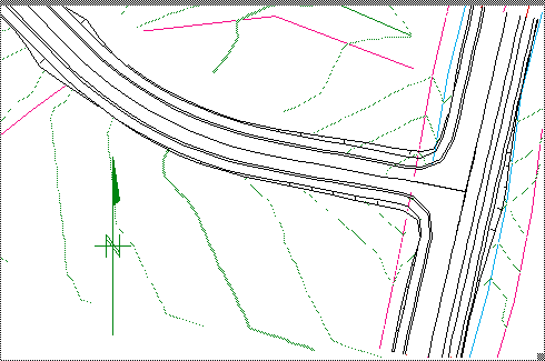
When you first add a Plan frame to the drawing, it will show a
view similar to that shown in the plan view when it was last visible.
That is the scale, orientation and co-ordinates at centre of frame
will match the plan view.
The frame can be dragged by the thick line at the top border
(similar to a window title), and can be resized by dragging the box
in the lower right corner. The view displayed in the frame can be
dragged from anywhere within the content region of the frame. The
cursor will change to a hand shape when over the picture. This allows
you to adjust which part of the plan is visible in the frame.
When the Plan frame is selected you can choose Get Object Info...
(from the edit menu). A dialog box as shown
Figure 17-5 will appear. You can set
information such as scale, rotation, the co-ordinates at the centre
of the frame and, if required, a grid at spacings set by you. You can
choose what details of the terrain model that you wish to show in the
Plan frame. You can show or hide the triangles, contours (at the
interval you specify) and features. The pop-up menu allows you to
choose which control lines that you want to appear in the Plan frame.
Control lines that will appear in the Plan frame are shown in italic.
For each control line you can choose what information about the
control line will be displayed in the Plan frame and how chainages
will be shown. Any other information is taken from the current plan
view.
Figure
17-5
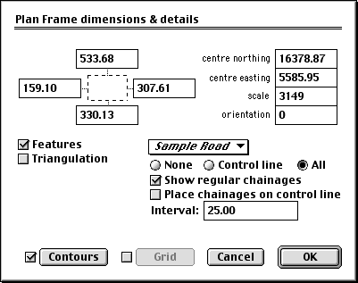
You can add more than one plan frame to any drawing. For example
you could have one frame at 1:5000 showing an overview, and another
frame at 1:500 showing a detail of part of this project.
Profile
frame tool

 When you add a
profile frame a profile of the current control line will be drawn.
When you add a
profile frame a profile of the current control line will be drawn.
The Profile frame needs to be tall enough to allow for the data
block under the Profile plot. The plot of the profile will be stepped
to fit into the height of the frame. The start chainage will match
the start chainage set in the Get Object Info... dialog box, and the
end chainage will be the end chainage set, or as much as can be
fitted in the frame. As you change the size of the profile frame it
will step the profile and include as many datum steps as are
necessary. Using the Get Object Info... command you can set the
scale, exaggeration, start and end chainage, and choose from the
pop-up menu which control line to display in this frame.
Cross
Section frame tool

 When you add a
Cross Section frame a series of cross sections of the current control
line will be drawn. As you expand or shrink this the number of cross
sections that can fit will be adjusted to suit. Choose Get Object
Info... to set the start and end chainages, scale and vertical
exaggeration as well as the frame dimensions.
When you add a
Cross Section frame a series of cross sections of the current control
line will be drawn. As you expand or shrink this the number of cross
sections that can fit will be adjusted to suit. Choose Get Object
Info... to set the start and end chainages, scale and vertical
exaggeration as well as the frame dimensions.