|Creative Engineering
home page|
|Table of contents |
Learning HighRoad |
Using HighRoad|
Reference|
| Previous |
Next |
Designing
a building pad and dam

In preparation for the next part of the tutorial you should create
another file to work with.
Note: If you have taken a break between tutorial
sections, you first need to Open the appropriate file.
* Open the file named Tutorial Part 4.rdd.
* Choose Save as... from the File menu.
* Name the file Tutorial Part 5.rdd.
You will now learn how to design a building pad and a dam. There
are three main elements in designing a building pad:
* specifying its shape, size and location
* determining its interaction with the natural surface
* modelling the terrain after the design is completed.
Each building pad you design is represented by a control line.
Despite the name, building pads can represent construction works
other than building pads. You can design dams, quarries, or any other
earthworks that need a flat area with slopes up and down to the
existing surface.
* Choose Fit to window from the View menu.
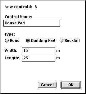
* Choose New control line... from the Plan menu.
A dialog box as shown in Figure 2-30
will appear.
* Type House pad in the space provided next to
Name.
* Click Building pad.
* Click OK.
This tells HighRoad that you want to design a building pad named
House pad. The initial dimensions of the building pad will be a
rectangle 15 m by 25 m.
Figure
2-30
You can now position the building pad on the terrain model. The
cursor will change to a cross when it is over the Plan window.
* Drag the cursor, being sure to remain entirely
within the terrain model while dragging.
A rectangle of the size of the pad will appear centred on the
cursor.
* Continue to drag the building pad until it is
halfway between point number 2 and point number 8.
* Release the mouse button when the building pad is positioned at
the desired location.
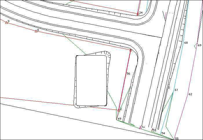
The building pad (including batter slopes) will be drawn on the
screen as shown in Figure 2-31.
Figure
2-31
* Move the cursor so that it is over the
building pad.
The cursor will change to a hand shape ( ) which indicates that you can drag the pad.
* Drag the pad to different locations to see how the
batter slopes are redrawn to suit the terrain in the new location.
When you have finished return the building pad to the position
shown in Figure 2-31. The location of the
pad in Figure 2-31 is very close to the
boundary line between point 7 and 8 and the batter slope is very
close to the boundary. The building pad would fit better in this area
if the width and length were swapped, and its orientation aligned
with the boundary.
* Double-click on the pad when the cursor is a hand
shape.
A dialog box will appear as shown in Figure
2-32. This is similar to the dialog box shown in
Figure 2-30 but with additional information
about the elevation and orientation of the building pad.
Figure 2-32
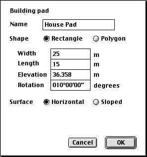
* Change the width to 25 m and the
length to 15 m.
* Set the elevation to 37 m.
* Set the orientation to 10 degrees.
* Click OK.
Note: You could achieve the same
position simply by adjusting the orientation to 100 degrees.
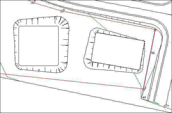
The building pad will be redrawn in the new position.
Estimating
earthworks quantities
* Note the direction of the rills on the batter
slope.
Rills are always attached to the high end of the batter slope. In
this example, the building pad is almost entirely in fill as can be
seen from the direction of the rills on the batter slopes, which are
attached to the pad and slope down towards the ground.
You can see the volume of earthworks required for this building
pad by displaying the Text window and listing the earthworks.
* Choose Text from the Windows menu .
An empty document will be displayed.
* Choose List Quantities from the Text menu.
The earthworks will be shown as no cut and about 480 m3 of fill.
Note: The volume listed in your example may be
slightly different because the location of your building pad may not
be exactly the same.
* Choose Save... from the File menu.
Note: If you have HighRoad S, only one pad can be
designed for each project. To follow this tutorial open the file
Tutorial Part 2.rdd again. As you proceed with the tutorial please
note that the first pad will not be shown.
Designing a dam
* Choose New control line... from the Plan
menu.
* Name the pad Farm dam.
* Select Building pad to specify the type of control line
required.
* Change the width and length to 20 m.
* Click OK.
The cursor will change to a cross when it is over the Plan window
so you can now position the dam.
* Drag the dam to the left (west) and down hill from
the house pad between point numbers 8 and 9.
* Release the mouse button when the building pad is positioned at
the desired location.
The dam (including batter slopes) will be drawn on the screen. The
ground level near the dam is approximately 34 m. The pad elevation
(i.e. the bottom of the dam) needs to be below ground level.
* Double-click on the dam.
* Set the elevation to 33 m in the dialog box that appears.
* Click OK.
* Look at the batter slope on the southwest corner of the dam.
Figure
2-33
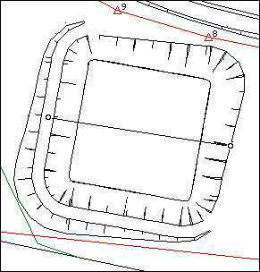
The narrow batter slope (as shown in Figure
2-33) indicates that the ground level near this corner of the dam
is much lower than around the rest of the dam. The maximum water
level you could have in the dam is limited by this low level. To
allow for a greater water capacity you can create an earth wall
around part of the dam where the ground is lower. To do this you need
to change the typical section of the dam. The typical section
determines the interaction of the building pad (in this case, the
dam) with the natural surface.
Creating a dam wall
When a building pad is first created it is assigned a simple
typical section shape which allows for a batter slope of 50% for both
cuts and fills. In the case of the dam you need to allow a similar
arrangement when the dam is in cut, but provide for a dam wall when
it is in fill, or only just below the ground level. The height of the
wall will be determined by the minimum depth of the dam required. In
this case the required depth is 2 m therefore the minimum wall height
required is 2 m above the bottom of the dam. If the dam floor is 2 m
or more below ground level, a batter slope (as described above) up to
the ground is required. When the dam floor is less than 2 m below the
ground, or above the ground, a wall is required. The wall width will
be 2 metres and batter slopes of 50%.
* Select Typical Section from the Window menu.
Figure
2-34
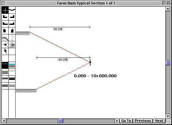
A window named Farm dam Typical Section 1 of 1 will appear on your
screen (see Figure 2-34). The marker in the
centre of the window represents the control line for the dam, with
the dot representing the level of the control line and the point at
which the batter slope attaches. The typical section shown is the
standard one which allows for a batter slope of 50% for both cuts and
fills. The right side of the typical section represents the flat
surface of the pad and left side represents the slopes up and down to
the ground surface. You need to replace the down batter slope with a
set of links that go up 2 metres and across 2 metres before the down
slope is commenced. First you need to undo some of the existing
links.
Designing a different typical section
* Choose Undo twice to remove the two batter
slopes.
Note: If you choose Undo more than
twice, the dot representing the level of the control line and the
point at which the batter slope attaches will disappear. This dot
(split point) must be in place before you can proceed. See Chapter
23, Troubleshooting,
Plan view
problems.
* Click on the cross cursor ( ) to select it.
The cross cursor is used where no edge type is required.
* Click the untreated surface ( ) to select it.
This generic surface type is used where an untreated surface type
is required.
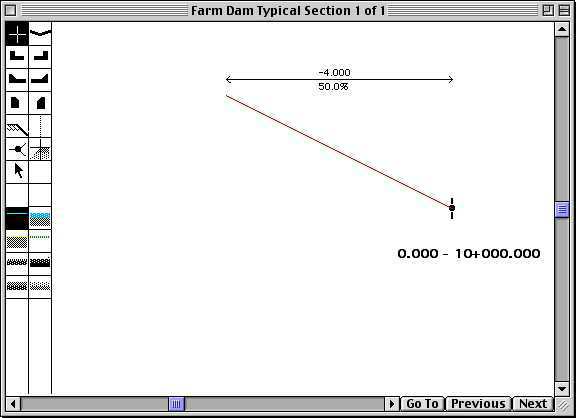
* Position the cursor to the left of the control line.
Drag the cursor to a position 4 m to the left of the control
line with a crossfall of 50.0%.
* Release the button when the slope is in the right location.
Note: If you release the button before the link
is located correctly you can change it. Click on the offset and
crossfall of the slope you have drawn. A dialog box will appear. You
can type in the required offset and crossfall.
Your typical section should now be similar to
Figure 2-35.
The next task is to add a horizontal link of offset 2 metres.
This will be link number 4. (Links are numbered in the order in which
they are entered.)
Note: Building pad typical sections have two very
short links of 1 mm each attached to the control point. The links you
add will be numbered starting with 3.
Figure
2-35
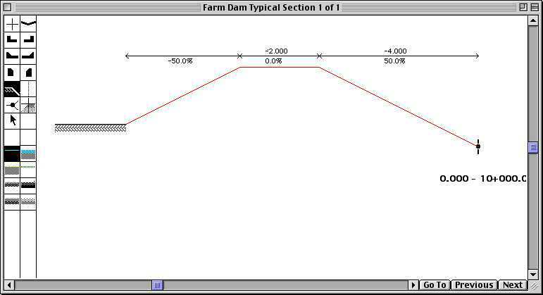
* Position the cursor and drag it to the
correct location (2 m offset, 0.0% crossfall).
The next task is to add a batter slope down at 50%. This will be
link number 5.
* Click on the batter slope ( ).
).
* Add a batter slope down at 50%.
Note: If you make an error while setting up the
typical section, correct it.
* Choose Undo from the Edit menu.
You have added 3 links so far. Your typical section should now be
similar to Figure 2-36. If the dam floor is
above the ground level, or as much as 2 metres below the ground level
a wall will be created. You now need a batter slope to cover the case
when the dam floor is more than 2 metres below ground. This is simply
a slope up at 50%.
Figure 2-36
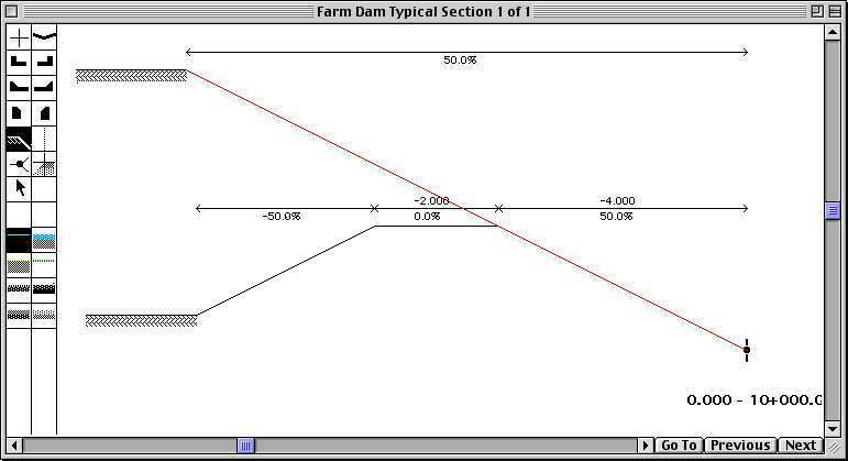
* Click on the batter slope ( ) again.
* Add a batter slope up at 50%.
You have now completed the typical section. You should now have a
typical section similar to Figure 2-37.
Figure
2-37
* Choose Plan from the Window menu.
* Examine the dam.
Figure
2-38
You can see in Figure 2-38
that a dam wall has been inserted where the ground level is not high
enough to allow the full 2 m depth. The extent of the dam wall is
easy to see from the 2 m wide flat strip on top of the dam wall, with
batter slopes running down either side of this. The batter slopes
from the wall overlap the southern property boundary. The location of
the dam can be dragged and/or the orientation changed until it fits
within the boundary.
* Double-click on the dam to change the orientation to
10 degrees.
* Drag the dam so that its batter slopes do not encroach on
property boundaries (as shown in Figure
2-39).
To assess the cost of construction of this project you can look at
earthworks volumes of both the house pad and the dam. By adjusting
the position, orientation and elevation of the dam and/or the house
pad you can change the quantities until they are balanced, thus
minimising the cost of construction.
Estimating the water volume of dam
The water volume can be estimated by using a road control line to
represent the water surface.
* Choose New control line from the Plan Menu.
* Name the control line Water surface.
* Select Road as the type of control line.
* Click OK.
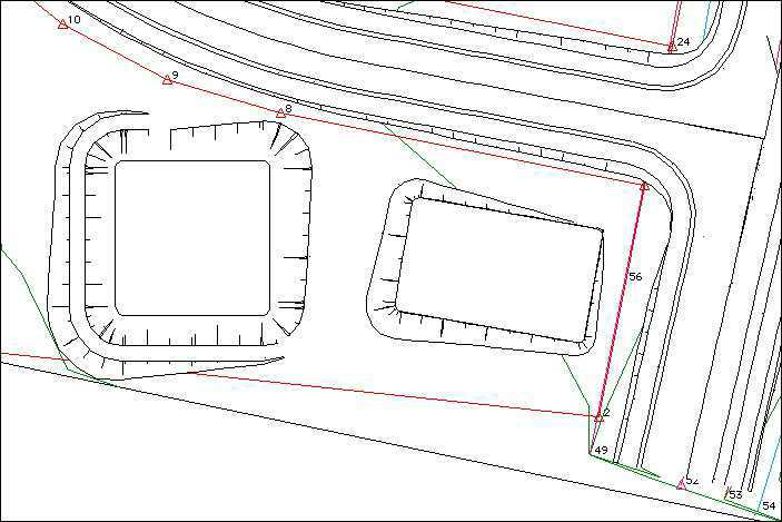
The control line for the water surface is to go from left to right
across the dam, from the middle of the dam wall on the left, to the
top of batter slope on the right, as shown in
Figure 2-39.
Figure
2-39
* Choose New IP from the Plan menu.
The cursor will change to a cross.
* Click to place the left end of the control line on
the dam wall.
* Choose New IP again.
* Click to place the right end of control line near the top of the
batter slope.
The elevation of this control line will be the water level. Recall
that the floor of the dam is elevation 33 m, and the walls are 2 m
high. Allowing for 200 mm freeboard this would mean a water level of
34.8 m. Create a design profile for a water level of 34.8 m.
* Choose Profile from the Window menu.
* Choose Show IP Location from the Profile menu.
* Choose New IP from the Profile menu.
* Locate the first IP at chainage 0 and elevation
34.8.
* Locate the second IP past the end and at elevation
34.8.
* Double-click each IP if necessary to precisely locate it.
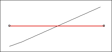
The profile should appear similar to Figure
2-40. The shape of the dam is not yet shown in the profile.
Figure
2-40
Construct the dam
To calculate the water volume, the dam needs to be constructed.
This will incorporate the shape of the dam into the natural surface.
Before you do this, save the work you have done and then make a copy
of it to use for constructing the dam.
* Choose Save from the File menu.
* Choose Save as... from the File menu.
* Name the file Tutorial Project 5 constructed.rdd.
* Choose Farm Dam from the Active menu.
* Choose Construct Farm Dam from the Plan menu.
* Click Construct.
* Choose Contours... from the Plan menu.
* Set the interval to 0.2 minor and 1.0 major.
* Observe the new contours showing the dam.
* Choose Water surface from the Active menu.
* Choose Profile to see the new shape of the ground
surface.
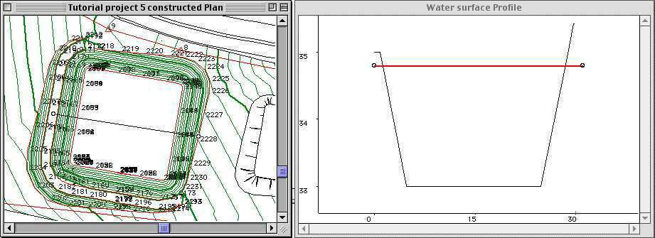
The new ground surface is clearly evident in
Figure 2-41 in both plan and profile.
Figure 2-41
Calculating the volume of water
To calculate the volume of water you need to design a suitable
typical section design.
* Choose Typical Section from Window menu.
* Choose Clear Typical Section from Typical Section menu.
* Select the cross cursor ( ) as the edge type.
* Select the untreated surface ( ) as the surface type.
* Draw a horizontal link 1 m each side of control point.
* Add a split point on each side.
* Select the batter edge type.
* Draw a horizontal batter each side.
* Click on the chainage range and change to 0 - 1000.000.
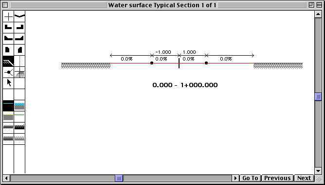
The typical section should look like that shown in
Figure 2-42. The typical section is
designed to represent a horizontal surface. The batter slopes will
extend horizontally until they strike the dam wall. To verify this
inspect some cross sections.
Figure
2-42
* Choose Cross Section Plot from
the Window menu.
* Click Next and Previous to see the cross sections.
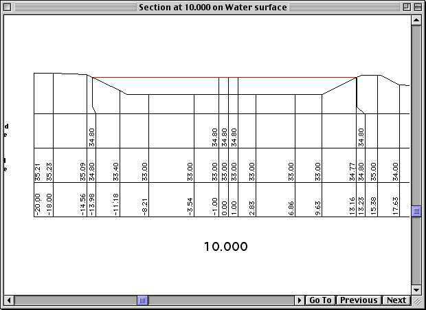
Figure 2-43 shows an example of a cross
section at chainage 10.000 m.
Figure
2-43
To estimate the water volume, calculate the earthworks quantities
for this control line. In this case the fill volume will represent
the water.
* Choose Schedule of Quantities from the Window
menu.
* Choose Limits from the Quantities menu.
* Click OK.
The full extent of the control line will be used.
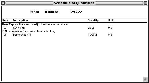
The quantity listed as Borrow to Fill is equivalent to water
volume (see the Schedule of Quantities in
Figure 2-44).
These quantities are based on cross sections at 5 metre intervals.
If you require more precision, go to the cross section plot window
and set the cross section interval to a smaller value, such as 1
metre.
* Choose Save from the File menu.
Figure
2-44
Printing your
design

To print, plot or export your design, you can use the drawing
manager to layout the drawing sheets. See
Chapter 17, Drawing production for
details. To plot or print this design, see
Chapter 18, Printing and
Chapter 19, Plotting.
| Previous |
Next |
Copyright 2001 Creative Engineering